In brief
Engineering guide for network telemetry and automation covering gNMI, NETCONF/YANG, observability, rollback, and operating evidence.
Key takeaways
- Australian enterprise AI adoption is accelerating. Colocation operators are designing GPU-dense halls with liquid cooling and high-density power racks to serve sovereign AI training and inference workloads.
- Remote Direct Memory Access over Converged Ethernet version 2, or RoCE v2, has become the default transport for GPU cluster backends.
- This is why lab validation matters before any production cable is pulled.
Why Australian MSPs Need a Lab-First Approach to AI Fabric Deployment
Australian enterprise AI adoption is accelerating. Colocation operators are designing GPU-dense halls with liquid cooling and high-density power racks to serve sovereign AI training and inference workloads. The OCP Podcast’s interview with David Hirst, CEO of Macquarie Data Centres, described a shift from traditional colocation-as-real-estate to chip-out design thinking, where the GPU and its network requirements drive facility architecture. For MSPs and integrators serving this market, the network fabric connecting GPU nodes is no longer a background detail. It is a make-or-break layer.
Remote Direct Memory Access over Converged Ethernet version 2, or RoCE v2, has become the default transport for GPU cluster backends. It allows GPUs to exchange model parameters, gradients, and activation data with near-zero CPU involvement and sub-microsecond latency on a well-tuned fabric. But RoCE v2 is also unforgiving. Packet loss on a RoCE v2 path does not just slow throughput; it stalls GPU synchronization and can collapse distributed training jobs entirely.
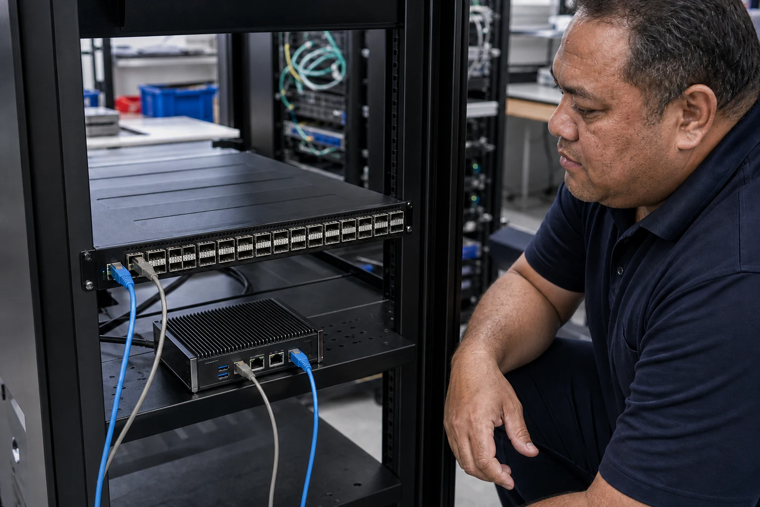
This is why lab validation matters before any production cable is pulled. For MSPs and integrators evaluating open SONiC-based switching as an alternative to proprietary AI fabric stacks, a structured lab test plan is the mechanism that builds confidence with enterprise buyers. It proves that the fabric can deliver lossless transport under realistic load, and it surfaces configuration issues before they become production incidents.
What SONiC Brings to the AI Fabric Table
Software for Open Networking in the Cloud, or SONiC, is an open-source network operating system maintained under the Linux Foundation and the SONiC Foundation. According to the SONiC Foundation, SONiC runs on switches from multiple vendors and ASICs, offers a full suite of network functionality including BGP and RDMA, and has been production-hardened in the data centers of large cloud service providers. Its container-based architecture provides fault isolation and simplified upgrades, which matters when you are managing a fabric that must stay online during training runs that can last days or weeks.
The Open Compute Project lists SONiC as a networking sub-project alongside ONIE and SAI (Switch Abstraction Interface). This ecosystem alignment means that hardware choices are decoupled from software choices. An MSP can select switching ASICs that match the port density, buffer depth, and RDMA queue requirements of the target GPU cluster, then run SONiC as a consistent NOS across the fabric.
For Australian buyers, this decoupling has a strategic dimension. Sovereign AI programs want infrastructure that does not lock them to a single vendor’s roadmap or pricing model. Open networking with SONiC provides an escape valve: if one switch vendor raises prices or falls behind on 400G/800G port availability, the NOS moves to the next compatible platform without retraining operations staff on a new CLI.
The Core RoCE v2 Fabric Behaviors That Must Be Lab-Tested
A lab test plan for a SONiC-based RoCE v2 AI fabric should validate the following fabric behaviors. Each one maps to a specific risk that, if unaddressed, can degrade GPU cluster performance in production.
Priority Flow Control and Lossless Transport
RoCE v2 relies on Priority Flow Control, or PFC, defined in IEEE 802.1Qbb, to create lossless queues on Ethernet links. When a switch egress buffer approaches congestion, it sends a PFC pause frame upstream, telling the sender to hold traffic on the affected priority queue. The lab must verify that PFC engages correctly under load, that pause frames propagate end-to-end across all leaf and spine hops, and that no queue starvation causes head-of-line blocking on unrelated traffic classes.
ECN and Congestion Notification
Explicit Congestion Notification, or ECN, works alongside PFC to signal congestion before buffers fill. Data Center Bridging Capability Exchange Protocol, or DCBX, negotiates these parameters between switches and endpoints. The lab should confirm that ECN marking thresholds are set correctly for the target buffer depth, that ECN-marked packets are honored by the RDMA transport layer, and that the fabric does not oscillate between PFC pause and ECN marking in a way that creates microbursts or throughput instability.
Fast Congestion Notification Profile
Fast CNP, or Congestion Notification Profile, is a mechanism to accelerate the feedback loop between congestion detection and RDMA sender rate adjustment. In a GPU cluster where thousands of flows contend for the same fabric paths, Fast CNP helps prevent congestion from cascading. The lab should validate that CNP generation and response times are within acceptable bounds and that the fabric recovers from induced congestion events without sustained throughput loss.
Telemetry and Visibility Under Load
In-band Network Telemetry, or INT, and IPTPath telemetry provide real-time visibility into queue depths, hop-by-hop latency, and path selection across the fabric. For MSPs, this telemetry is critical for post-deployment troubleshooting and SLA monitoring. The lab test plan should include telemetry validation: confirm that INT data is being generated at every hop, that a collector or packet broker can ingest and export the telemetry stream, and that the data correlates with actual congestion events induced during testing.
EVPN-VXLAN Overlay for Multi-Tenant GPU Clusters
When a single fabric serves multiple GPU cluster tenants or multiple AI workload types, EVPN-VXLAN provides tenant isolation and flexible workload placement. The lab should validate that VXLAN encapsulation does not introduce unacceptable latency overhead for RoCE v2 traffic, that EVPN route distribution is correct, and that tenant isolation holds under load.
A Phased Lab Test Plan Framework
The following framework gives MSPs and integrators a structured path from bench setup to pre-production sign-off. Each phase should produce documented results that can be shared with the end customer as evidence of fabric readiness.
Phase 1: Hardware and SONiC Image Validation
- Confirm that all switch models in the fabric bill of materials are on the SONiC supported devices list.
- Install the target SONiC image on each switch and verify boot, interface discovery, and management plane connectivity.
- Validate optical transceiver compatibility for all port types: SFP28 for 25G host connections, QSFP28 for 100G leaf-spine links, and QSFP-DD or OSFP for 400G spine links where applicable.
- Run basic L2/L3 connectivity tests across all planned fabric links.
Phase 2: RoCE v2 Baseline and PFC/ECN Tuning
- Configure lossless queues, PFC, and ECN parameters per the GPU NIC vendor’s recommended settings.
- Use traffic generators to simulate RDMA read and write patterns at line rate.
- Verify that PFC pause frames propagate end-to-end without uncontrolled packet drop.
- Tune ECN marking thresholds and PFC deadlock timers based on observed buffer utilization.
- Document all parameter settings and the rationale for each tuning decision.
Phase 3: Congestion and Stress Testing
- Induce controlled congestion by oversubscribing specific fabric paths and observing PFC, ECN, and CNP behavior.
- Run multi-flow stress tests that simulate hundreds of concurrent RDMA flows across multiple GPU nodes.
- Measure tail latency, throughput distribution, and fabric recovery time after congestion events.
- Validate INT and IPTPath telemetry output against observed congestion events.
Phase 4: Resilience and Failure Injection
- Simulate link failures, switch reboots, and transceiver removals during active RDMA traffic.
- Verify that the fabric reconverges without sustained GPU application errors.
- Test PFC storm scenarios where a downstream port failure causes upstream buffer accumulation.
- Validate that BGP or other routing protocols reconverge within acceptable timeframes.
Phase 5: Pre-Production Integration
- Connect actual GPU nodes running representative AI training workloads to the lab fabric.
- Run a short distributed training job and measure collective operation latency (AllReduce, AllGather) across the fabric.
- Confirm that telemetry data from the fabric correlates with GPU NIC performance counters.
- Produce a final lab report with pass/fail status for each test case and recommended production configuration.
Australian Market Considerations
Several factors make this lab-first approach especially relevant for Australian MSPs and integrators.
Data sovereignty and compliance. Australian enterprise buyers, particularly in government, financial services, and healthcare, have data sovereignty requirements that favor local infrastructure over offshore cloud GPU services. Building and validating a sovereign AI fabric locally gives MSPs a differentiated offering. The OCP Podcast episode featuring David Hirst of Macquarie Data Centres highlighted how Australia’s sovereign approach to AI infrastructure is shaping colocation design, with an emphasis on local compliance as a market advantage.
Supply chain and lead times. Australian data center programs face longer hardware lead times than North American or European counterparts due to geographic distance from major manufacturing hubs. A lab test plan that validates the complete bill of materials early in the project lifecycle reduces the risk of discovering incompatibilities after switches and optics have already shipped.
Skills and partner ecosystems. The Australian MSP and integrator market is smaller than the US or UK market, which means hands-on SONiC and RoCE v2 experience is less widespread. A documented lab test plan serves as a training artifact: it gives the operations team a repeatable process they can use for future deployments, and it gives the end customer confidence that the integrator has validated the fabric methodically rather than relying on trial-and-error in production.
What This Means for xSONiC Buyers
xSONiC’s data center AI switch portfolio is designed for exactly this kind of validation-driven deployment. By combining open SONiC-based switching with AI fabric and RoCE v2 solution guidance, xSONiC gives MSPs and integrators a platform they can lab-test thoroughly before committing to production deployment. The GPU backend fabric solution pillar provides architectural reference designs, while DCBX, Fast CNP, and INT telemetry solutions cover the specific fabric behaviors that the lab test plan validates.
For Australian programs evaluating open networking for GPU cluster backends, the lab test plan framework above is not optional. It is the proof path. It turns an open networking promise into a documented, reproducible result that enterprise buyers can trust.
Engineering Evidence Floor
For telemetry and automation topics, accept the design only when state, change, and incident evidence are connected. The evidence package should include gNMI or NETCONF/YANG support, telemetry cadence, collector location, alert thresholds, config source of truth, rollback, packet visibility, retention, and escalation ownership. A practical pilot should run 24 hours of streaming telemetry, include 3 automated changes, and prove that an incident bundle can be produced within 2 hours.
| Evidence area | What to validate | Acceptance gate | Rework trigger |
|---|---|---|---|
| State export | gNMI/OpenConfig, NETCONF/YANG, counters, and optics data | 24 hours telemetry stream retained | Dashboards lose data during faults |
| Change control | Source of truth, diff, validation, and rollback | 3 automated changes pass readback | Automation pushes config without proof |
| Incident view | Alerts, logs, packet feeds, and queue/drop counters | Root cause path identified within 15 minutes | Graphs show symptoms but not cause |
| Security | Access control, retention, audit trail, and sovereignty | 30 days evidence policy documented | Telemetry path violates data handling rules |
| Support | Escalation owner, evidence bundle, patching, and RMA | P1 package ready within 2 hours | Vendor handoff lacks data |
Engineering FAQ
What should be proven before adopting EVPN-VXLAN on SONiC? Prove underlay routing, BGP sessions, VTEP behaviour, MAC/IP learning, route scale, multi-homing design, failure convergence, and observability. The overlay should be accepted as a system, not a feature checkbox.
Why does the underlay design still matter in an overlay network? EVPN-VXLAN depends on a stable routed underlay. MTU, ECMP, addressing, route policy, link failure behaviour, and telemetry determine whether the overlay remains predictable under load and during faults.
What should be included in an EVPN-VXLAN operations runbook? Include naming, IP plan, BGP policy, VNI mapping, change process, rollback commands, failure checks, telemetry fields, backup and restore steps, and escalation ownership for the selected SONiC image.
Related xSONiC Resources
Sources Reviewed
- Ethernet Network Adapters - ConnectX NICs | NVIDIA
- NVIDIA BlueField Data Processing Unit
- NVIDIA Spectrum-X Ethernet Platform
- ACSC Essential Eight
- OAIC Notifiable Data Breaches
- APRA CPS 234 Information Security
- NETSCOUT Network Packet Definition
- Cloudflare Network Packet Definition
- SONiC Project Documentation
- Broadcom Ethernet Switching
- Marvell Switching
- NVIDIA Ethernet Switching
- Open Compute Networking
- SONiC GitHub
- SONiC Foundation
Product fit
Products referenced for evaluation
These products are referenced for evaluation context in the article. Confirm workload, port, optics, software, interoperability, and support requirements against the exact deployment before procurement.
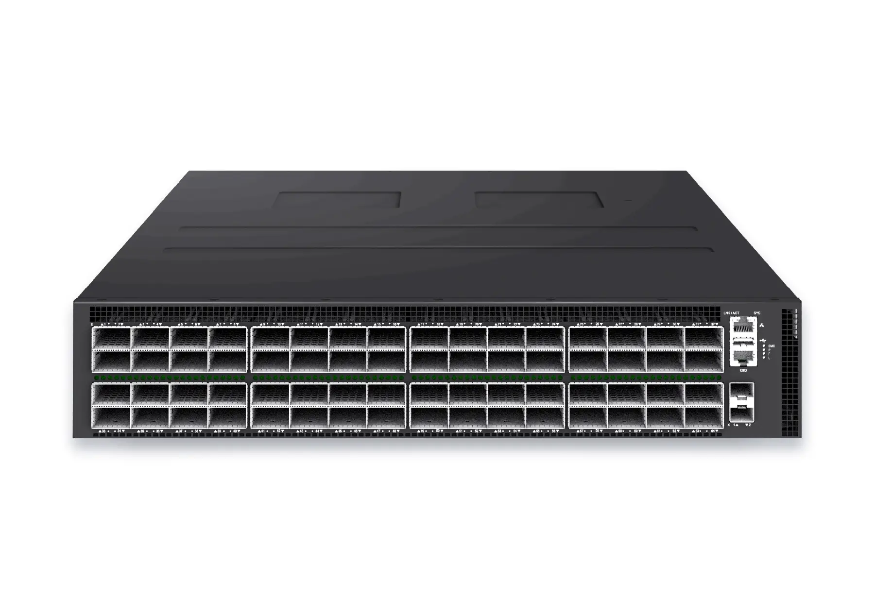 datacenter aiXS-DC-64X800-AI-G164-port 800G AI fabric switch for large-scale GPU clusters, HPC backbones, and ultra-high-throughput data center networks.View product
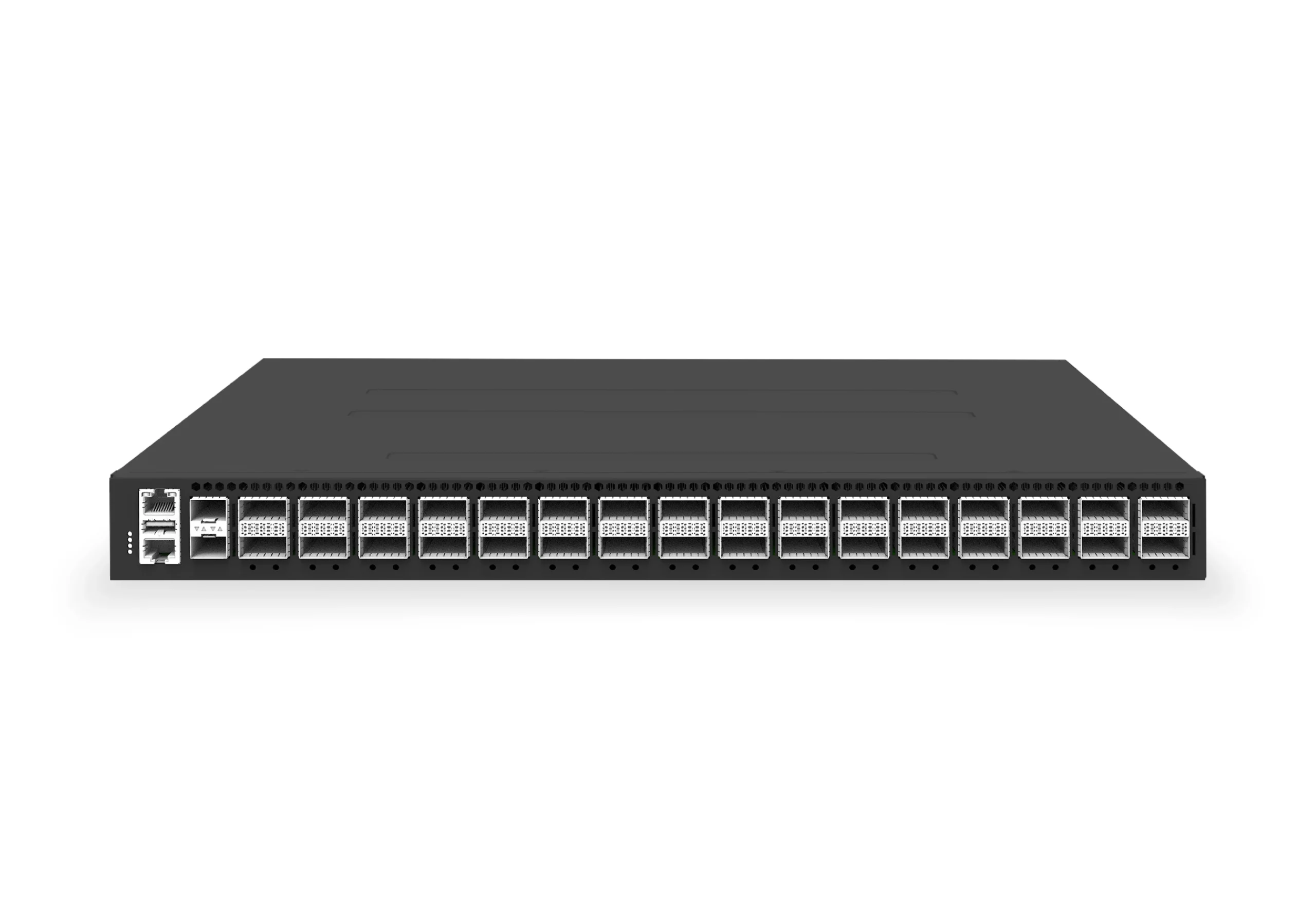 datacenter aiXS-DC-32X400-SP-G232-port 400G spine/core switch for high-capacity data center fabrics and AI-ready backbones.View product
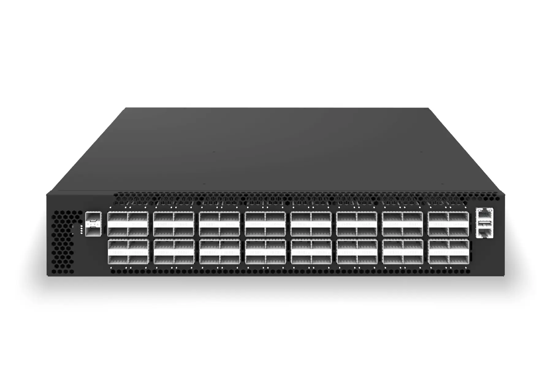 datacenter aiXS-DC-64X200-LS-G164-port 200G leaf/spine switch for high-bandwidth storage, compute, and scale-out data center fabrics.View product
Continue reading
Related articles
 Technical ArticleHow SONiC-Powered 400G and 800G Switches Change AI Data Center Fabric Design in AustraliaEngineering guide for 400G and 800G optics planning covering form factor, reach, telemetry, thermal limits, supply risk, and validation.Read article
 Technical ArticleRoCE v2 GPU Backend Fabrics at 400G and 800G: What Australian Data Center Operators Need to Know in 2026Engineering guide for AI fabric buyers covering RoCE, SONiC, telemetry, optics, support ownership, and deployment validation.Read article
 Technical ArticleWhat Australian Data Center Buyers Need to Know Before Choosing SONiC Switches for 400G and 800G UpgradesEngineering guide for 400G and 800G optics planning covering form factor, reach, telemetry, thermal limits, supply risk, and validation.Read article