Australian-made deployment scope
Architecture review, solution configuration, validation planning, documentation, and commercial accountability are handled in Australia.
Data Center Solution
Coordinate PFC, ETS, and application priority discovery for RDMA-ready networks.
Data Center Bridging Exchange (DCBX) is the negotiation layer used by adjacent Ethernet devices to discover and align Data Center Bridging behavior. It rides on LLDP and exchanges lossless Ethernet parameters such as Priority Flow Control (PFC), Enhanced Transmission Selection (ETS), and application priority mappings.
For xSONiC data center fabrics, DCBX matters most when RoCEv2, storage, HPC, or AI training traffic needs predictable low-loss forwarding. These workloads can be sensitive to packet loss, retransmission, queue pressure, and inconsistent priority treatment across servers and switches.
DCBX is not a complete QoS policy by itself. It is a discovery and exchange mechanism that helps devices understand the DCB capabilities and intended configuration on the other side of a link.
| Function | What It Does | Operational Value |
|---|---|---|
| Peer discovery | Learns DCB capabilities and configuration from the adjacent device. | Reduces blind spots during server-to-switch and switch-to-switch bring-up. |
| Configuration exchange | Shares PFC, ETS, and application priority information. | Helps align lossless classes and bandwidth treatment across the link. |
| Change monitoring | Tracks local and peer-side DCB changes. | Helps operators detect drift after maintenance or policy updates. |
| Technology | Role in a Lossless Fabric | Typical xSONiC Use |
|---|---|---|
| PFC | Pauses selected priority classes instead of pausing the entire link. | Protects RDMA/storage classes from packet loss under congestion. |
| ETS | Allocates bandwidth and scheduling treatment among traffic classes. | Keeps lossless classes from starving normal traffic, and vice versa. |
| Application Priority | Maps specific applications or protocols to traffic priorities. | Aligns RoCEv2, storage, and management traffic with intended queues. |
| LLDP | Carries DCBX information between directly connected neighbors. | Provides the transport for link-local DCBX exchange. |
DCBX uses LLDP extension TLVs to carry DCB information. The LLDP TLV type is vendor-specific, with IEEE DCBX information identified by the IEEE OUI. The payload then identifies which DCBX subtype is being exchanged.
| TLV | Subtype | Typical Length | Purpose |
|---|---|---|---|
| ETS Configuration TLV | 0x09 | 25 bytes | Advertises ETS parameters and bandwidth allocation. |
| ETS Recommendation TLV | 0x0A | 25 bytes | Carries recommended ETS values for the peer. |
| PFC Configuration TLV | 0x0B | 6 bytes | Exchanges PFC enablement and capability information. |
| Application Priority TLV | 0x0C | Variable | Maps applications to traffic priorities. |
DCBX behavior can be understood as a per-port state machine. Each enabled port collects local configuration, advertises it, reads peer information, updates local state when policy allows, then keeps monitoring for changes.
| State | Processing | Next Step |
|---|---|---|
| Local configuration collection | Read local DCB settings, capability, and willingness. | Advertise locally if a peer exists; otherwise monitor for changes. |
| Local configuration advertisement | Send local DCBX information to the adjacent device. | Collect peer configuration if negotiation is allowed. |
| Peer configuration collection | Read peer capability, willingness, and advertised DCB settings. | Decide whether local state should be updated. |
| Local configuration update | Reconcile local and peer DCB configuration according to policy. | Return to monitoring after convergence. |
| Configuration change monitoring | Watch for local or peer-side changes. | Restart collection when state changes are detected. |
Local DCB policy
      |
      v
Collect local PFC / ETS / APP priority settings
      |
      v
Advertise settings through LLDP DCBX TLVs
      |
      v
Receive peer DCBX TLVs
      |
      v
Compare willingness, capability, and priority mappings
      |
      v
Apply accepted updates or keep local policy
      |
      v
Monitor for link, peer, or policy changesConsider a server connected to an xSONiC leaf switch. If the switch has PFC enabled for the RDMA priority but the server NIC does not, congestion can still lead to packet loss. The switch may send PFC pause frames, but the endpoint will continue transmitting if it has not negotiated or enabled the same lossless behavior.
Misaligned configuration

Server NIC          xSONiC Leaf
PFC disabled  --->  PFC enabled on RDMA priority
Traffic keeps       Switch buffer fills under congestion
transmitting        Packet loss or retransmission risk increases
With DCBX enabled on both sides, the server and switch can exchange DCB capability and configuration information before the workload depends on that link. Operators still need to define the intended QoS policy, but DCBX reduces the chance that each link carries a different interpretation of the same traffic class.
Aligned DCBX exchange

Server NIC <--- LLDP DCBX TLVs ---> xSONiC Leaf
     |                                  |
     +-- PFC / ETS / APP priority -----+
     +-- Capability and willingness ---+
+-- Monitoring after convergence -+DCBX is also useful beyond the server edge. In a leaf/spine or storage fabric, switches may need to keep PFC and ETS behavior consistent along the forwarding path. When two switches advertise incompatible priority treatment, DCBX can surface the difference and, where policy permits, help one side accept the peer’s configuration.
For xSONiC deployments, this is especially relevant across:
Use DCBX as part of a deliberate QoS design, not as a substitute for one.
DCBX planning is most important on xSONiC data center switches that participate in RoCEv2, storage, HPC, or AI backend fabrics. It is a natural fit for 100G, 200G, 400G, and 800G leaf/spine designs where small inconsistencies can become expensive once large-scale traffic starts.
DCBX, PFC, ETS, and ECN should be validated as one congestion-control system. In the lab, run at least 3 traffic classes, 2 lossless priorities, one oversubscription event, and one mis-marked host profile. Capture queue depth, pause frames, ECN marks, CNP rate where applicable, and drops per priority.
| Check | Evidence to collect | Reject condition |
|---|---|---|
| Priority mapping | Host NIC, switch queue, DSCP/PCP, and DCBX state snapshots. | RDMA or storage traffic lands in the wrong queue. |
| Congestion response | ECN marks, PFC pause duration, queue depth, and flow completion time. | Pause propagation spreads beyond the intended lossless class. |
| Operational rollback | Known-good QoS profile, rollback command, and post-rollback counters. | The team cannot return to a stable profile in one maintenance window. |
No. DCBX exchanges Data Center Bridging capability and configuration, but the lossless behavior still depends on the QoS design, host NIC settings, queue mapping, PFC policy, ETS allocation, and ECN thresholds. Treat DCBX as the negotiation layer inside a broader congestion-control system.
Verify that the host NIC and xSONiC switch agree on the RDMA or storage traffic priority, the queue mapping, and the enabled PFC classes. Then run a controlled oversubscription test and confirm that queue depth, pause frames, ECN marks, and drops match the intended policy.
Australian-Made Deployment Scope
Architecture review, solution configuration, validation planning, documentation, and commercial accountability are handled in Australia.
Switching, optics, storage, server, and packet visibility components are selected against port speed, OS, telemetry, power, and deployment requirements.
The bill of materials is checked against RFP requirements, rollback path, optics compatibility, support model, and export screening before order release.
xSONiC supports international buyers through Australian project ownership, acceptance evidence, documentation, and post-delivery escalation.
Related Products
Use these related platforms as a starting point for sizing, comparison, and follow-up discussion.
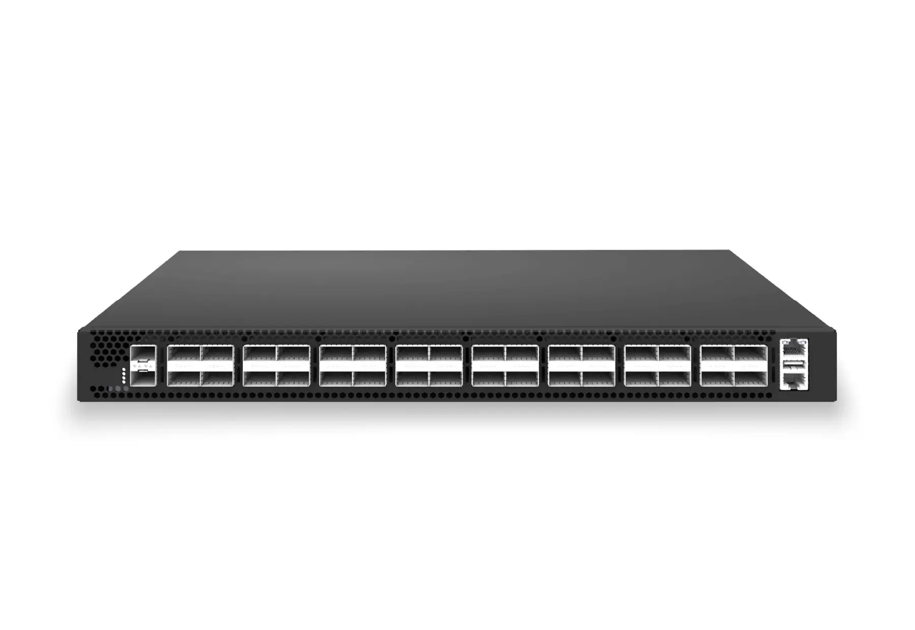
32-port 100G leaf/spine switch for compact data center fabrics, cloud routing, and high-throughput server aggregation.
32-port 100G leaf/spine switch for VXLAN fabrics, RoCE-ready workloads, and tenant-scale routing.
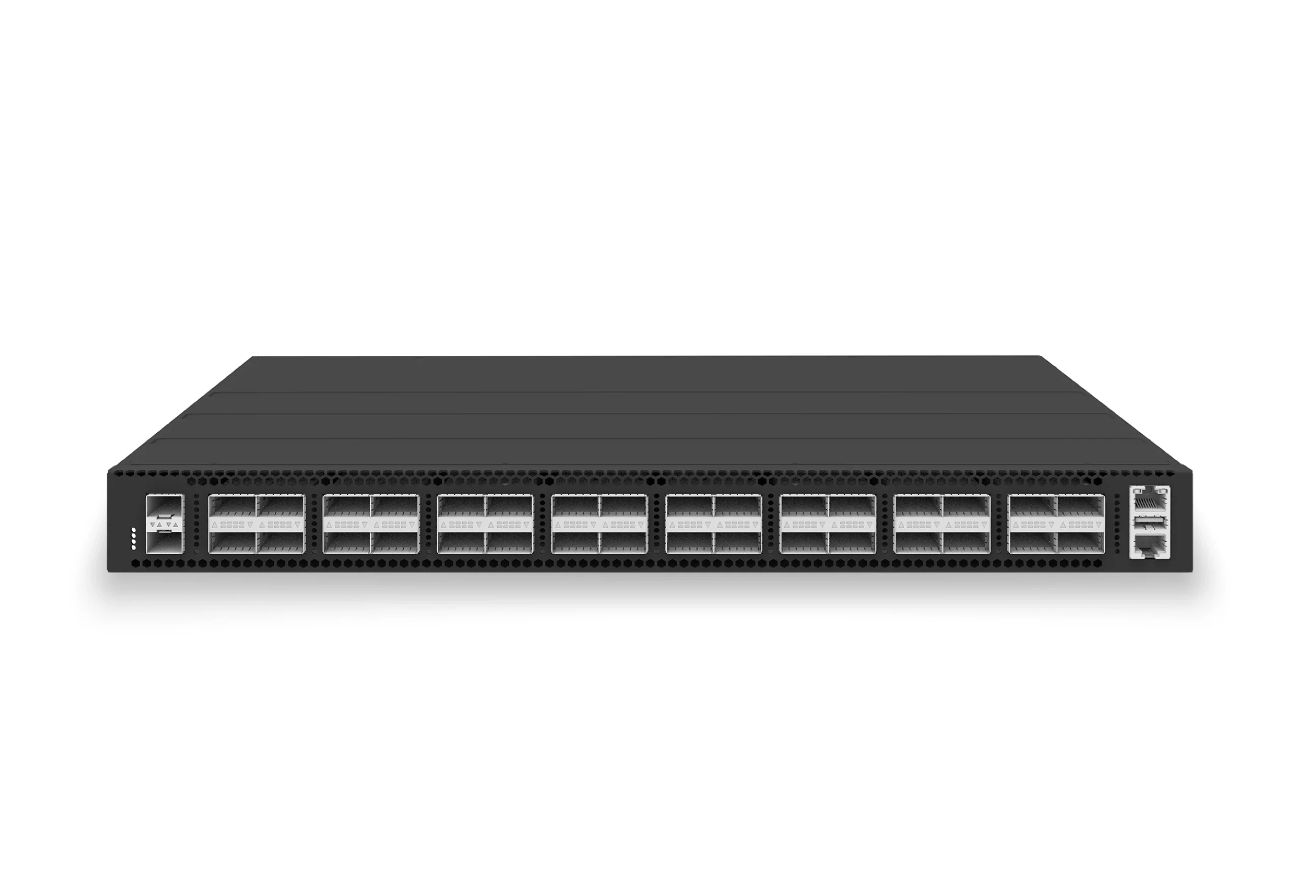
32-port 400G spine/core switch for high-capacity data center fabrics and AI-ready backbones.
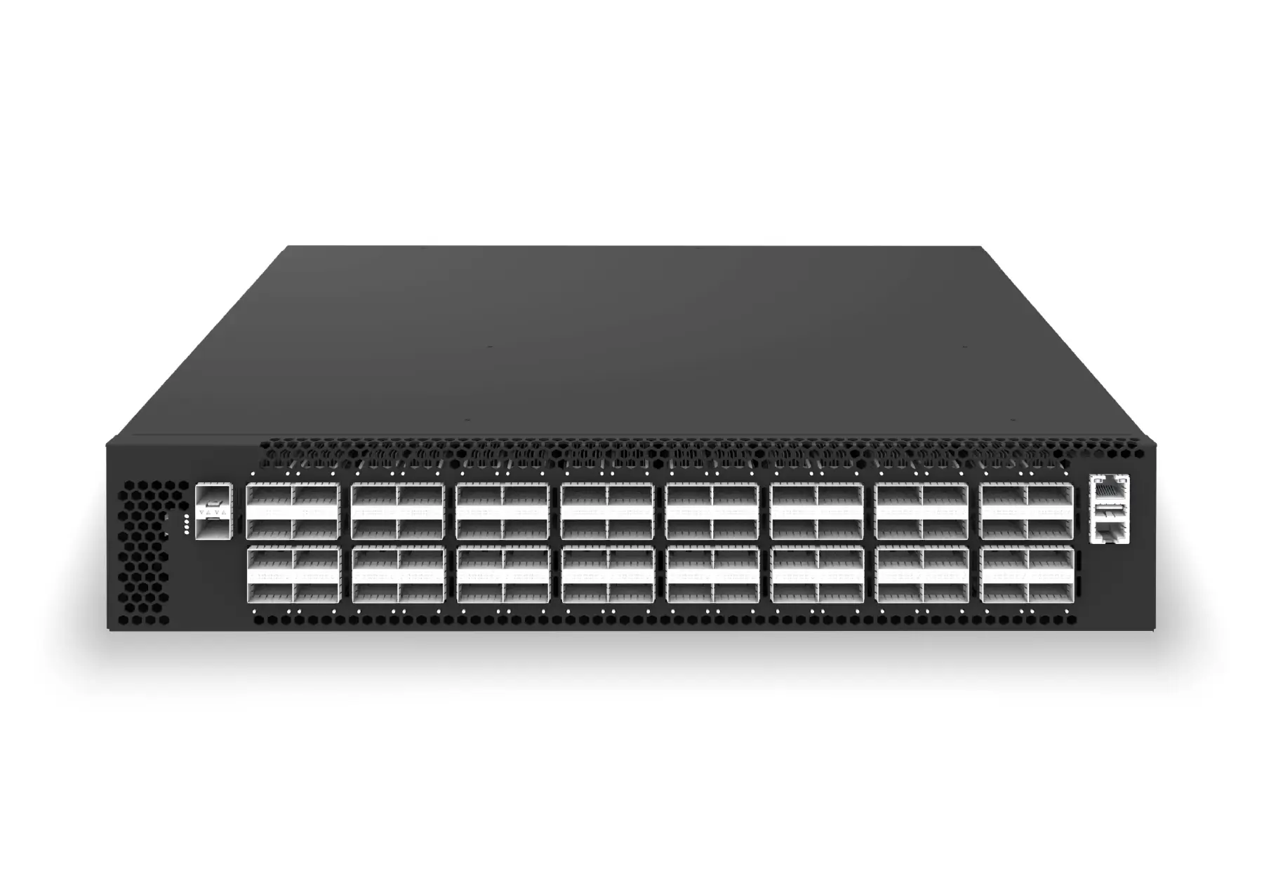
64-port 200G leaf/spine switch for high-bandwidth storage, compute, and scale-out data center fabrics.
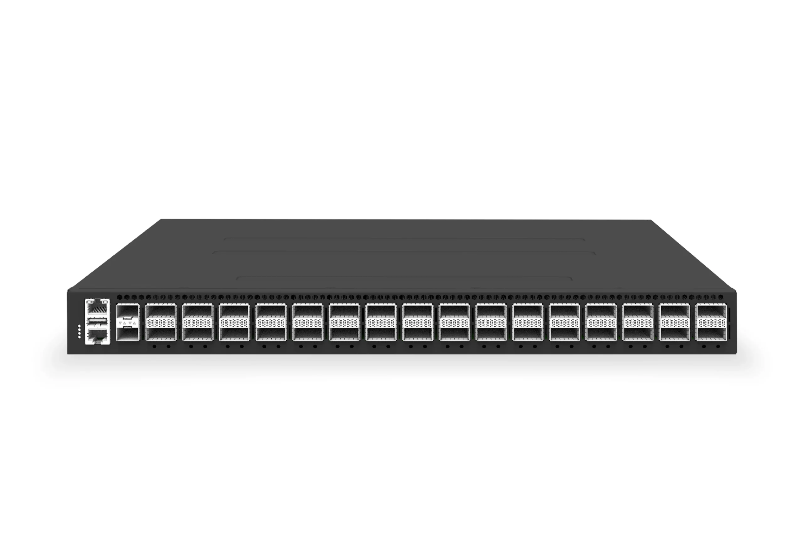
64-port 800G AI fabric switch for large-scale GPU clusters, HPC backbones, and ultra-high-throughput data center networks.
Use the related products below to continue comparing platforms, or open a conversation if you need help mapping the solution to your environment.