In brief
An engineering guide to packet, flow, and telemetry visibility in AI data center Ethernet fabrics, with validation criteria for Australian GPU cluster deployments.
Key takeaways
- AI data centre visibility is not the same as ordinary enterprise monitoring.
- The minimum visibility stack has three layers: packet evidence, flow evidence, and switch telemetry.
- Traditional monitoring often watches internet edges, firewalls, and WAN links.
Engineering Position
AI data centre visibility is not the same as ordinary enterprise monitoring. GPU backend fabrics generate high-volume east-west traffic, bursty incast patterns, and congestion-sensitive flows where a small amount of packet loss or queueing can reduce job throughput. Australian enterprises building private inference or training infrastructure need to prove that the fabric is observable before it carries critical workloads.
The minimum visibility stack has three layers: packet evidence, flow evidence, and switch telemetry. A packet broker helps deliver scoped packet feeds to tools; IPFIX-style flow records provide summarised traffic patterns; INT, path telemetry, and switch counters explain forwarding behaviour inside the fabric.
Why AI Fabrics Create Different Visibility Requirements
Traditional monitoring often watches internet edges, firewalls, and WAN links. AI fabrics shift the problem inside the data centre:
- East-west dominance: GPU nodes exchange gradients, embeddings, checkpoints, and storage traffic across leaf-spine paths.
- High link speed: 100G, 400G, and 800G links can exceed the ingest capacity of conventional security and packet-capture tools.
- Loss sensitivity: RoCEv2 and RDMA-like designs depend on correct queueing, PFC, ECN, DCBX, and congestion handling.
- Short failure windows: microbursts and transient drops may not appear in coarse polling intervals.
- Overlay complexity: VXLAN or EVPN designs can hide workload identity unless the visibility layer can inspect inner headers.
In this environment, “we collect SNMP counters” is not enough. The team needs evidence at the point of loss, congestion, or path change.
Visibility Layers and What Each One Answers
| Layer | What it answers | Limitation |
|---|---|---|
| Packet capture | What exactly crossed this observation point? | Expensive at 100G/400G/800G if unfiltered. |
| Packet broker | Which packet feeds go to which tools, with what filters and loss accounting? | Does not explain every switch-hop queue condition by itself. |
| Flow telemetry / IPFIX | Who talked to whom, how much, and when? | Usually lacks full payload and packet timing detail. |
| INT / path telemetry | Which path did traffic take, and where did queueing or congestion appear? | Requires fabric support and collector integration. |
| Device counters | Which interface, queue, buffer, or port is dropping or pausing traffic? | Polling interval can miss microbursts. |
RFC 7011 defines IPFIX as a standard way to export measured traffic information from observation points. RFC 791, RFC 8200, RFC 9293, and RFC 768 define the IP, TCP, and UDP fields that packet and flow tools use for classification. For overlay fabrics, RFC 7348 and RFC 7432 are important because they define VXLAN and EVPN behaviour that the monitoring layer must understand.
Where to Instrument an AI Ethernet Fabric
Leaf-to-GPU/server links. These links reveal endpoint behaviour: noisy nodes, retransmissions, MTU mismatches, and workload-specific flow patterns.
Leaf-to-spine links. These links reveal fabric utilisation, ECMP distribution, incast pressure, and oversubscription.
Storage and checkpoint paths. AI workloads often separate training traffic from storage or management traffic. Visibility must distinguish them to avoid blaming the wrong domain.
Border and cloud on-ramp links. Inference platforms may exchange data with external services, object storage, or cloud regions. These paths need security and performance visibility.
Packet broker egress ports. Tool delivery is itself a monitoring point. If the broker drops on egress because a tool is saturated, the production fabric may be healthy while the visibility fabric is not.
What to Validate Before Production
| Validation area | Evidence to capture |
|---|---|
| Mirror/TAP coverage | Diagram of every observation point and the flows it can see. |
| Packet broker filters | Output pcaps proving the correct rack, VLAN, VNI, IP range, or protocol reaches each tool. |
| RoCE visibility | Counters for PFC, ECN marking, drops, queue occupancy, and relevant traffic class behaviour. |
| Flow correlation | IPFIX or flow records matched to packet captures for a known workload run. |
| Telemetry correlation | INT/path telemetry matched to device counters and packet captures during a congestion test. |
| Tool capacity | Evidence that packet capture, NDR, IDS, and analytics tools do not oversubscribe during workload peaks. |
| Failure behaviour | Link loss, optic replacement, switch process restart, and tool backpressure tests. |
The most useful test is a workload-like run. Generate or schedule traffic that resembles the target AI job, then inspect whether telemetry, packet capture, and tool counters tell the same story.
Packet Brokers in AI Visibility
In AI fabrics, packet brokers should usually operate out of band. They receive copies from TAPs, switch mirroring, or visibility ports, then filter and deliver traffic to tools. Inline inspection in the GPU backend path should be avoided unless the bypass and failover behaviour has been explicitly engineered.
Useful broker policies include:
- Filter by GPU rack, tenant VNI, VLAN, or workload IP range.
- Slice packets for long-retention metadata while preserving full packets for short incident windows.
- Load balance packet capture across multiple collectors without breaking flow symmetry.
- Strip VXLAN or GRE outer headers when tools need inner workload fields.
- Export counters showing drops caused by broker policy versus tool congestion.
Australian Deployment Considerations
Australian AI teams often face a mix of data sovereignty, local support, and limited specialist network engineering availability. That makes visibility design part of risk management, not just operations. A fabric that requires rare expertise to debug under pressure is not production-ready.
For APRA-regulated entities, CPS 234 control testing and incident response evidence are relevant when AI infrastructure supports regulated workloads. For broader enterprise hardening, ASD Essential Eight projects often increase the need for reliable detection and investigation around privileged access, application control, and patching outcomes.
xSONiC Architecture Fit
xSONiC AI fabrics should be evaluated as a stack:
- Data center AI switches provide high-speed fabric ports.
- AI fabric design defines the topology and traffic classes.
- RoCE v2 guidance sets expectations for congestion-sensitive Ethernet.
- INT telemetry and IPTPath telemetry provide path and queue insight.
- Packet broker platforms deliver scoped packet evidence to downstream tools.
- AIDC controller can consume telemetry and help centralise fabric operations.
Bottom Line
AI fabric visibility has to be proven at packet, flow, and telemetry layers. The engineering question is not whether every packet can be stored forever; it is whether the team can capture the right packet evidence, correlate it with flow and telemetry data, and explain loss or congestion before it damages workload throughput.
Engineering Evidence Floor
For packet broker and traffic visibility topics, accept capacity claims only after replication, filtering, and tool delivery are modelled together. The evidence package should include source links, 95th percentile utilisation, burst peaks, tunnel handling, packet slicing or deduplication, replication factor, tool-port capacity, HA behaviour, and alert ownership. A useful pilot should replay 30 minutes of representative traffic, cover 100G/400G links where present, and include at least 3 failure or tool-overload cases.
| Evidence area | What to validate | Acceptance gate | Rework trigger |
|---|---|---|---|
| Source traffic | Link speed, burst peak, packet mix, and tunnel mix | Model covers current and 12 months growth | Average utilisation drives sizing |
| Replication | Copy count, filters, deduplication, slicing, and load balance | 30 minutes replay with rules enabled | Vendor proof uses clean traffic only |
| Tool delivery | IDS/NDR/SIEM ingress, loss counters, and failover | No sustained drops at broker or tool | Tools overload while broker is healthy |
| Resilience | HA, bypass, link failure, tool failure, and rollback | 3 failure cases documented | Visibility disappears during incidents |
| Audit | Evidence bundle, retention, access control, and ownership | P1 packet evidence ready within 2 hours | Teams debate which data is authoritative |
This section deliberately avoids treating the topic as a feature checklist. The buyer should be able to hand the evidence to engineering, security, finance, and support teams and have each group understand what was tested, what failed, what was accepted, and what still needs rework. That is also the content pattern most useful for generative search: the page states a clear conclusion, names measurable parameters, identifies risk, and cites the operational proof required before deployment.
Engineering FAQ
What should be measured before sizing a packet broker? Measure source link speed, 95th-percentile utilisation, burst peaks, replication factor, filter complexity, tunnel handling needs, and tool-port capacity. Packet broker sizing fails when it is based on average traffic rather than copied and filtered traffic.
What proves that a visibility design is production ready? The design should prove aggregation, filtering, replication, load balancing, packet slicing or deduplication if required, and tool failover under realistic traffic. Security teams should also verify that drops are reported rather than hidden.
Where do Australian buyers most often under-scope visibility projects? The common gaps are east-west data centre traffic, encrypted or tunneled flows, AI cluster bursts, retention requirements, and tool oversubscription. A procurement brief should model those before asking vendors for a bill of materials.
Related xSONiC Resources
Sources Reviewed
- Ethernet Network Adapters - ConnectX NICs | NVIDIA
- NVIDIA BlueField Data Processing Unit
- NVIDIA Spectrum-X Ethernet Platform
- ACSC Essential Eight
- OAIC Notifiable Data Breaches
- APRA CPS 234 Information Security
- NETSCOUT Network Packet Definition
- Cloudflare Network Packet Definition
- SONiC Project Documentation
- Broadcom Ethernet Switching
- Marvell Switching
- NVIDIA Ethernet Switching
- Open Compute Networking
- SONiC GitHub
- SONiC Foundation
Product fit
Products referenced for evaluation
These products are referenced for evaluation context in the article. Confirm workload, port, optics, software, interoperability, and support requirements against the exact deployment before procurement.
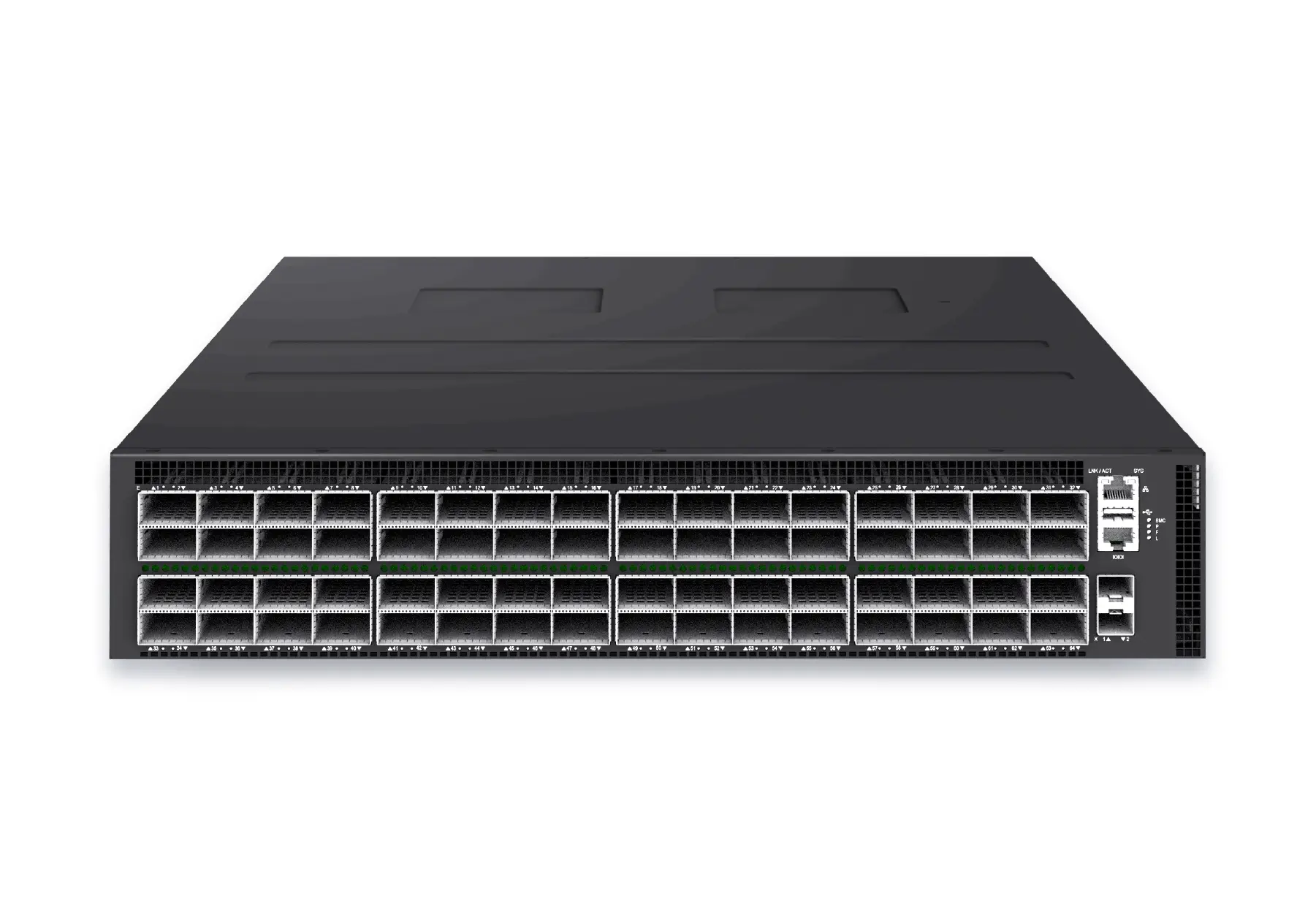 datacenter aiXS-DC-64X800-AI-G164-port 800G AI fabric switch for large-scale GPU clusters, HPC backbones, and ultra-high-throughput data center networks.View product
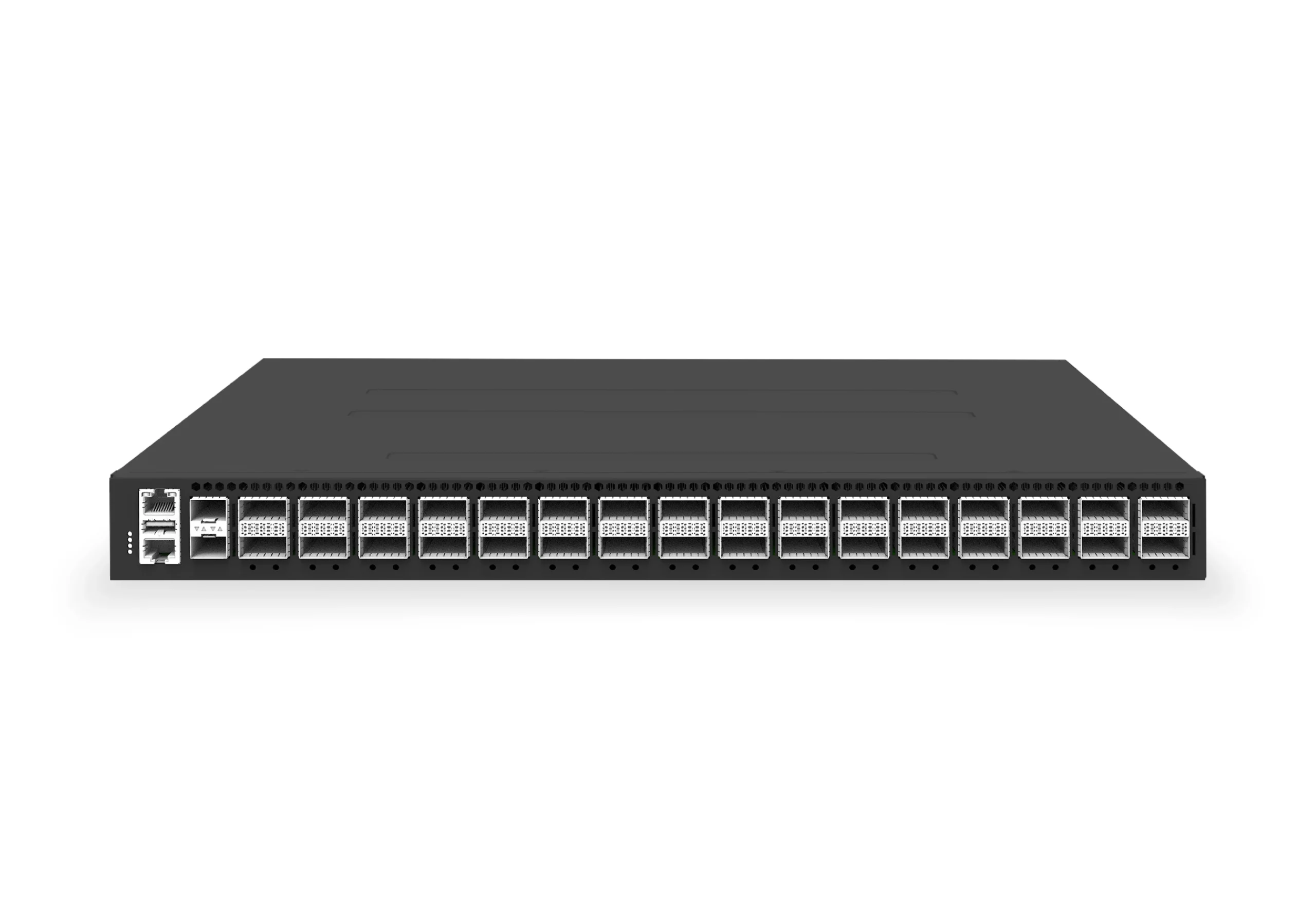 datacenter aiXS-DC-32X400-SP-G232-port 400G spine/core switch for high-capacity data center fabrics and AI-ready backbones.View product
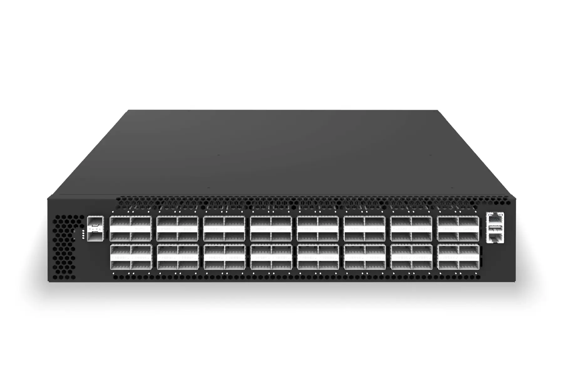 datacenter aiXS-DC-64X200-LS-G164-port 200G leaf/spine switch for high-bandwidth storage, compute, and scale-out data center fabrics.View product
Continue reading
Related articles
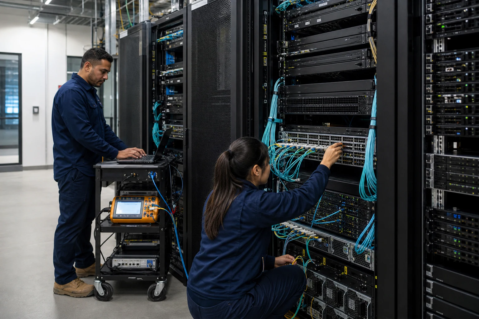 Technical ArticleHow SONiC-Powered 400G and 800G Switches Change AI Data Center Fabric Design in AustraliaEngineering guide for 400G and 800G optics planning covering form factor, reach, telemetry, thermal limits, supply risk, and validation.Read article
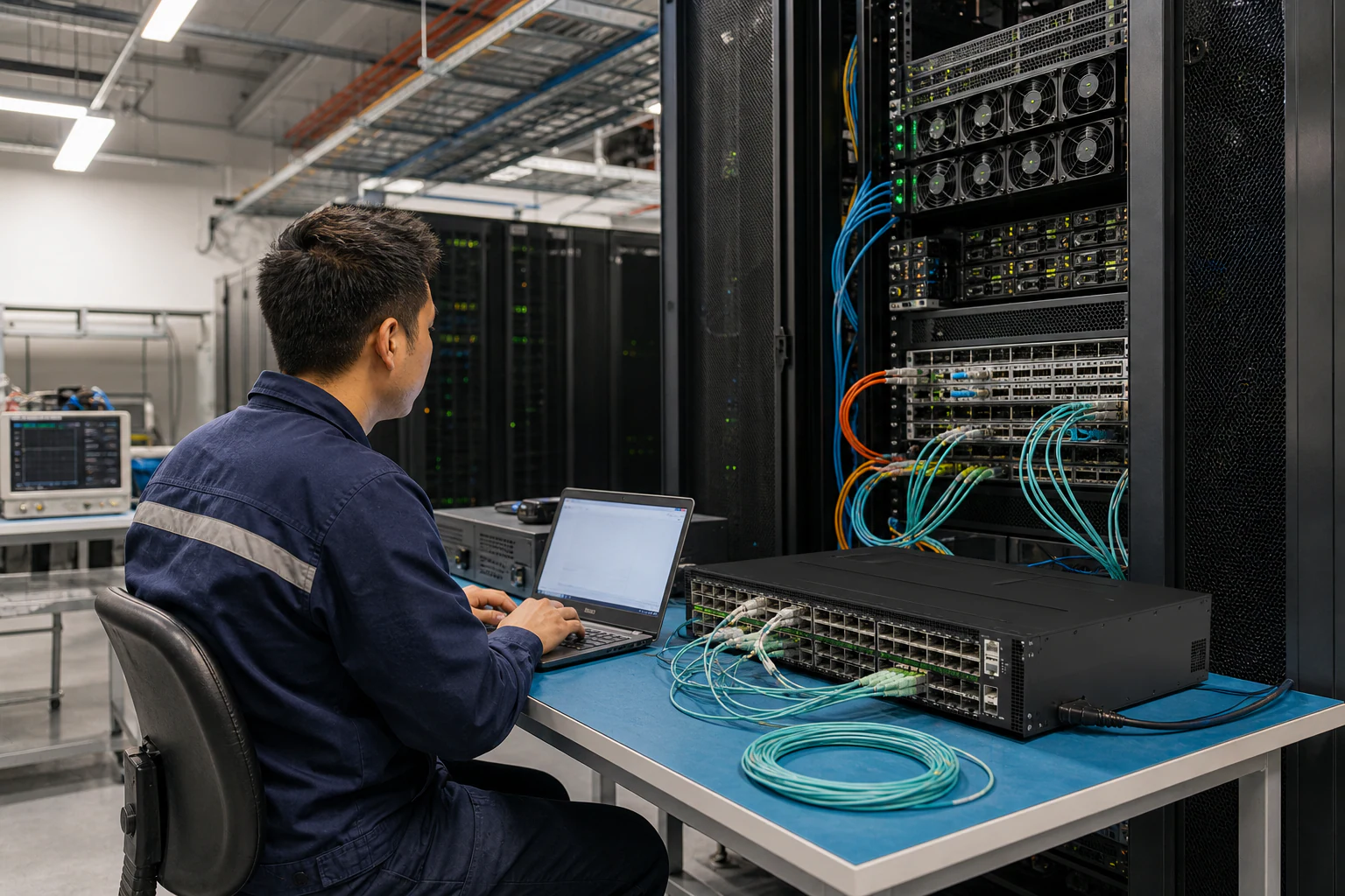 Technical ArticleRoCE v2 GPU Backend Fabrics at 400G and 800G: What Australian Data Center Operators Need to Know in 2026Engineering guide for AI fabric buyers covering RoCE, SONiC, telemetry, optics, support ownership, and deployment validation.Read article
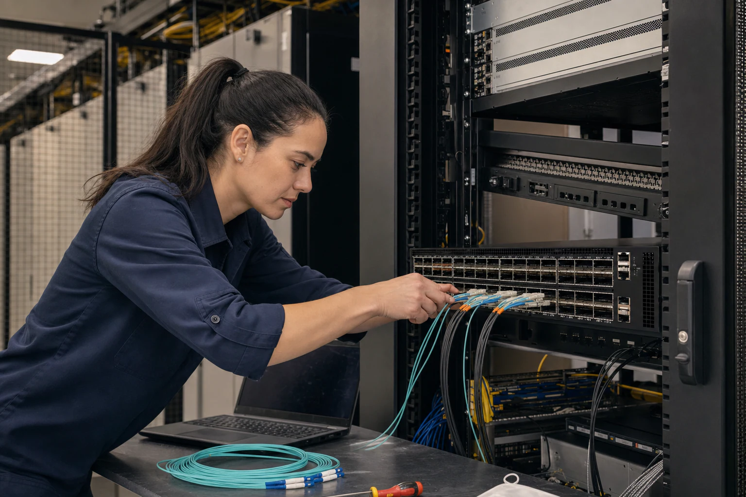 Technical ArticleWhat Australian Data Center Buyers Need to Know Before Choosing SONiC Switches for 400G and 800G UpgradesEngineering guide for 400G and 800G optics planning covering form factor, reach, telemetry, thermal limits, supply risk, and validation.Read article