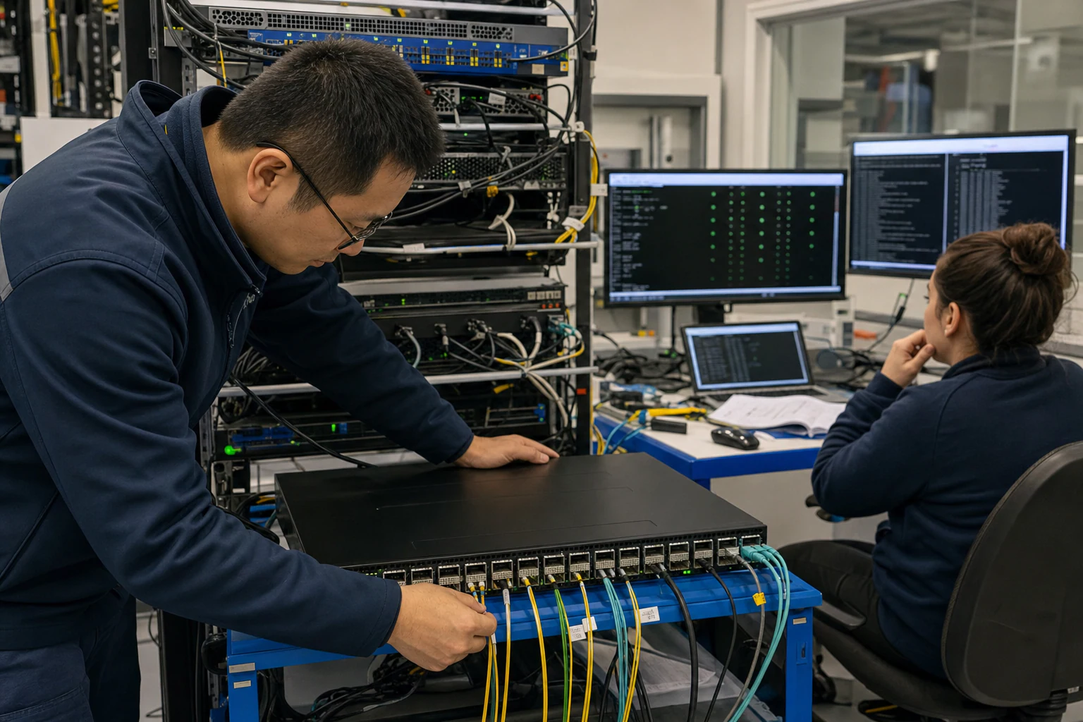
In brief
Engineering guidance on Traditional Data Center Networking Breaks Under AI Training Workloads for Australian infrastructure teams, covering form factor tradeoffs.
Key takeaways
- If you have managed a conventional data center network for any length of time, you know the playbook.
- When a GPU cluster runs a distributed training job, the network is not carrying polite, retry-friendly TCP sessions.
- This article explains what changes in the network when AI workloads arrive, why RoCE v2 over Ethernet has become the dominant transport, and how SONiC-based open switching gives buyers a practical path to building AI fabric without vendor lock-in.
The Networking Problem AI Creates That Most Buyers Do Not See Coming
If you have managed a conventional data center network for any length of time, you know the playbook. Spine-leaf architecture, ECMP load balancing, TCP-based traffic flows, and enough oversubscription headroom to absorb bursty east-west traffic. That model works well for web applications, virtual machines, and microservices.
AI training clusters break it.
When a GPU cluster runs a distributed training job, the network is not carrying polite, retry-friendly TCP sessions. It is carrying Remote Direct Memory Access (RDMA) traffic that expects near-zero packet loss, microsecond-level latency, and predictable throughput across hundreds or thousands of parallel flows. A single congestion event that a traditional network would absorb with a TCP retransmit can stall an entire training epoch, wasting hours of expensive GPU compute.
This article explains what changes in the network when AI workloads arrive, why RoCE v2 over Ethernet has become the dominant transport, and how SONiC-based open switching gives buyers a practical path to building AI fabric without vendor lock-in.
How a Traditional Data Center Network Handles Traffic
Traditional data center networks were designed around mixed application traffic, VM mobility, storage replication, and north-south service access. They can be highly reliable for those workloads because TCP absorbs loss, applications retry, and a few milliseconds of queueing usually does not destroy the business outcome.
In a conventional enterprise or cloud data center, traffic patterns are largely TCP-based. TCP provides reliable delivery through retransmission: if a packet is lost, the sender detects the gap and resends it. For web applications, databases, and general-purpose compute, this model works well because the small delay from a retransmit is invisible to the end user.
The spine-leaf topology that most modern data centers use replaced the legacy three-tier (core-distribution-access) model to reduce latency and improve east-west traffic handling. In a leaf-spine fabric, every leaf switch connects to every spine switch, creating a predictable two-hop path between any two endpoints. Equal-Cost Multi-Path (ECMP) routing distributes flows across all available spine links.
For general workloads, this architecture is efficient. For AI training, it is necessary but nowhere near sufficient.
What AI Training Traffic Actually Looks Like
A distributed AI training job splits a model across dozens or hundreds of GPUs. During each training step, the GPUs must synchronize gradients - the computed updates to model parameters - across the entire cluster. This synchronization happens via collective communication operations such as AllReduce, AllGather, and ReduceScatter.
These collectives have three properties that stress the network in ways conventional workloads do not:
- Incast patterns. Many GPUs send data to one GPU (or a small group) simultaneously, creating micro-bursts that can overflow switch buffers in microseconds.
- Large, synchronized flows. Gradient exchanges can be hundreds of megabytes per step per GPU. On a 256-GPU cluster, a single AllReduce can involve terabits of traffic arriving within the same narrow time window.
- Zero tolerance for retransmission delay. Unlike a web request where a 50 ms retransmit is unnoticeable, a stalled gradient exchange blocks every GPU in the group. The entire training step waits.
This is why AI clusters have converged on RDMA over Converged Ethernet version 2 (RoCE v2) as the transport protocol rather than TCP.
RoCE v2: Why Lossless Ethernet Matters for AI
RDMA allows one computer to directly access the memory of another without involving the operating system on either end. This bypasses the kernel networking stack, cutting latency from tens of microseconds (TCP) to low single-digit microseconds. RoCE v2 carries RDMA operations over standard UDP/IP Ethernet, which means it runs on conventional Ethernet switches - but with critical requirements.
RoCE v2 is sensitive to packet loss in a way that TCP is not. When a RoCE v2 packet is dropped, the recovery mechanism is significantly slower and more disruptive than TCP retransmission. A single lost packet can stall an RDMA queue pair, cascading delays across the entire collective operation.
To prevent this, the network must provide:
- Priority Flow Control (PFC). A mechanism defined in IEEE 802.1Qbb that allows a congested switch to send a pause frame upstream, temporarily stopping traffic on a specific priority class rather than dropping packets. This is the foundation of lossless Ethernet.
- Data Center Bridging Capability Exchange (DCBX). A protocol that negotiates PFC, ETS (Enhanced Transmission Selection), and other data center bridging parameters between switches and endpoints, ensuring consistent QoS behavior across the fabric.
- Explicit Congestion Notification (ECN) and Fast Congestion Notification (Fast CNP). Rather than waiting for PFC pauses (which can cause head-of-line blocking), modern AI fabrics use ECN marking to signal congestion early. Endpoints respond with Congestion Notification Packets (CNPs), throttling their send rate before buffers overflow. Fast CNP implementations reduce the reaction time to single-digit microseconds.
- Deep, intelligent buffering. AI fabric switches need larger and more dynamically managed buffers than typical data center switches. Shared buffer architectures that allocate buffer space based on real-time demand outperform statically partitioned designs.
This set of capabilities - PFC, DCBX, ECN, fast CNP-style endpoint feedback, queue telemetry, and validated buffer behavior - is what transforms a standard Ethernet switch into an AI fabric switch. The important point is that these features must be proven under load. A datasheet statement is not enough.
The Spine-Leaf Architecture for AI Fabric
AI training fabrics almost universally use a leaf-spine topology, but with important differences from a general-purpose deployment:
- Non-oversubscribed or very low oversubscription. Every leaf-to-spine link should be 1:1 or close to it. Any oversubscription creates a congestion hotspot that degrades collective operations.
- Rail-optimized or rail-attached topology. In large clusters (1024+ GPUs), the network is often designed so that GPUs on the same rail (the same network interface across multiple servers) connect to the same leaf switch. This reduces the number of hops for intra-rail traffic and simplifies congestion management.
- Consistent latency. AI collectives are latency-sensitive. Any variable latency across different paths through the fabric appears as stragglers, slowing the entire training step.
For Australian buyers evaluating AI fabric builds, the physical infrastructure matters as much as the switching silicon. Optical transceiver selection (SFP28 for 25G, QSFP28 for 100G, QSFP-DD or OSFP for 400G and 800G), cabling strategy (DAC for short rack-to-rack runs, AOC or fiber for longer inter-rack and inter-row links), and switch port density all determine whether the fabric can scale without forklift upgrades.
Where SONiC Fits: Open Networking for AI Fabric
SONiC (Software for Open Networking in the Cloud) is a Linux-based network operating system now hosted under the SONiC Foundation. It runs on switching hardware from multiple vendors, which means buyers can evaluate switching silicon and optics independently from the NOS, provided the platform implementation and SAI layer are validated.
For AI fabric deployments, SONiC offers several advantages:
- Open hardware abstraction. SONiC uses SAI as the southbound hardware abstraction layer, but buyers still need ASIC/SDK/version evidence for the exact platform.
- Containerized operations. SONiC services such as routing, LLDP, telemetry, and platform monitoring run in containerized modules, which changes how teams debug and upgrade the fabric.
- Multi-vendor hardware flexibility. Because SONiC is decoupled from switching hardware, buyers can evaluate different ASIC platforms and choose the one that matches latency, buffer depth, port density, and local supply requirements.
- Telemetry and visibility. AI fabric operations require queue depth, PFC pause counters, ECN/CNP events, link errors, optics DOM data, and per-flow/path visibility. SONiC is useful only if those counters are exposed reliably on the target platform.
For Australian enterprises and data center operators, the open networking model that SONiC enables is particularly relevant. The Australian data center market is growing rapidly, driven by cloud adoption, data sovereignty requirements, and increasing demand for AI compute capacity. SONiC-based switching reduces dependence on any single vendor’s pricing and roadmap, giving operators more control over their infrastructure economics and upgrade cadence.
A Practical Buyer Checklist for AI Fabric Evaluation
If your organization is planning or expanding an AI training or inference cluster, here are the network-level questions to answer before selecting infrastructure:
| Evaluation Area | What to Verify |
|---|---|
| Switching silicon | Does the ASIC support deep shared buffering, PFC, ECN, and wire-speed forwarding at your target port speed (100G, 400G, 800G)? |
| NOS capability | Does the network operating system support RoCE v2, DCBX, and Fast CNP with documented configuration guides? |
| Telemetry | Can the fabric stream INT data and queue-depth metrics to your monitoring platform in real time? |
| Topology flexibility | Does the solution support rail-optimized topologies and non-oversubscribed leaf-spine fabrics at your target scale? |
| Transceiver ecosystem | Are the required optical transceivers (SFP28, QSFP28, QSFP-DD, OSFP) and DAC/AOC cables validated with the switch platform? |
| Automation | Does the NOS expose APIs (REST, gNMI, NETCONF/YANG) for automated provisioning and day-2 operations? |
| Scalability path | Can the fabric grow from an initial pod (64-256 GPUs) to a multi-pod cluster (1024+ GPUs) without replacing the core switching platform? |
| Support and community | Is there vendor-backed support available in Australia, or a strong upstream community with enterprise SLAs? |
| Failure-mode evidence | Has the vendor shown behavior during link loss, optics errors, PFC storm conditions, queue buildup, warm reboot, and rollback? |
What This Means for Australian Data Center Buyers
The networking requirements for AI workloads are not an incremental step up from traditional data center switching. They represent a fundamentally different set of demands: lossless transport, microsecond congestion response, deep buffering, and high-density optical connectivity at 100G, 400G, and 800G.
The good news is that Ethernet AI fabrics are now a mainstream engineering path, not a lab experiment. UEC, OCP ESUN, IEEE 802.3, SONiC, and major silicon vendors are all pushing the ecosystem toward open, high-speed, lossless Ethernet for AI. The caution is equally important: buyers still need workload-specific proof before treating a general data center switch as an AI fabric switch.
For Australian enterprises, colocation providers, and managed service providers building AI infrastructure, the key is to start with the network fabric requirements and work outward to product selection - not the other way around. A GPU cluster is only as fast as the network that connects it.
Next steps: Explore xSONiC’s AI Fabric solution, RoCE v2 guide, and Data Center AI switches to see how open networking infrastructure maps to your AI cluster requirements. For a direct consultation, contact the xSONiC team.
Engineering FAQ
How should NVMe form factor selection be made? Start with workload profile, usable capacity, serviceability, thermal envelope, write endurance, PCIe generation, slot layout, and replacement process. U.2, E1.S, M.2, and AIC devices solve different mechanical and operational problems.
What matters more than peak sequential speed? Sustained performance, thermal throttling behaviour, write endurance, latency under load, firmware stability, power-loss protection, and fleet manageability usually matter more than a single benchmark number.
How should storage be validated for AI or cloud workloads? Test the selected form factor in the real chassis with expected airflow, queue depth, write mix, temperature range, and monitoring stack. Validation should include steady-state and recovery behaviour, not only fresh-drive performance.
Related xSONiC Resources
Sources Reviewed
- Ethernet Network Adapters - ConnectX NICs | NVIDIA
- NVIDIA BlueField Data Processing Unit
- NVIDIA Spectrum-X Ethernet Platform
- OpenConfig gNMI Specification
- OpenConfig
- RFC 7950 - The YANG 1.1 Data Modeling Language
- RFC 6241 - Network Configuration Protocol (NETCONF)
- SONiC Project Documentation
- Broadcom Ethernet Switching
- Marvell Switching
- NVIDIA Ethernet Switching
- Open Compute Networking
- SONiC GitHub
- SONiC Foundation
- Supports: SONiC container architecture, Redis state model, and SAI hardware abstraction.
- Supports: syncd, ASIC_DB, SAI API, and hardware-vendor SDK relationship.
- Supports: PFC as per-traffic-class flow control and current work on PFC/DCBX enhancements.
- Supports: AI Ethernet congestion behavior, RoCE congestion control, telemetry, and endpoint rate-control discussion.
- Supports: industry work on lossless, efficient, resilient Ethernet for AI scale-up networking.
- Supports: active 200G, 400G, 800G, 1.6T, and Ethernet-for-AI standards work.
Product fit
Products referenced for evaluation
These products are referenced for evaluation context in the article. Confirm workload, port, optics, software, interoperability, and support requirements against the exact deployment before procurement.
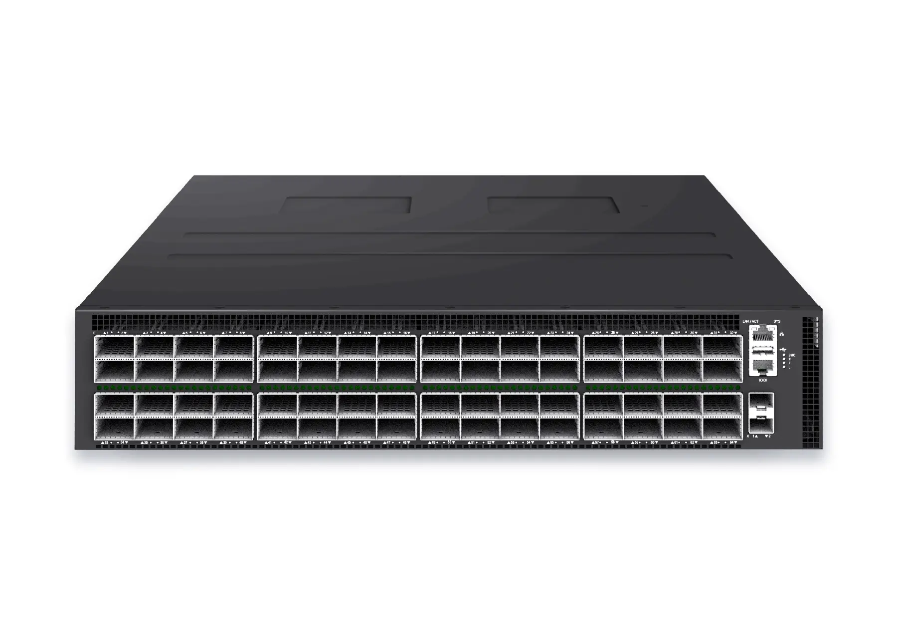 datacenter aiXS-DC-64X800-AI-G164-port 800G AI fabric switch for large-scale GPU clusters, HPC backbones, and ultra-high-throughput data center networks.View product
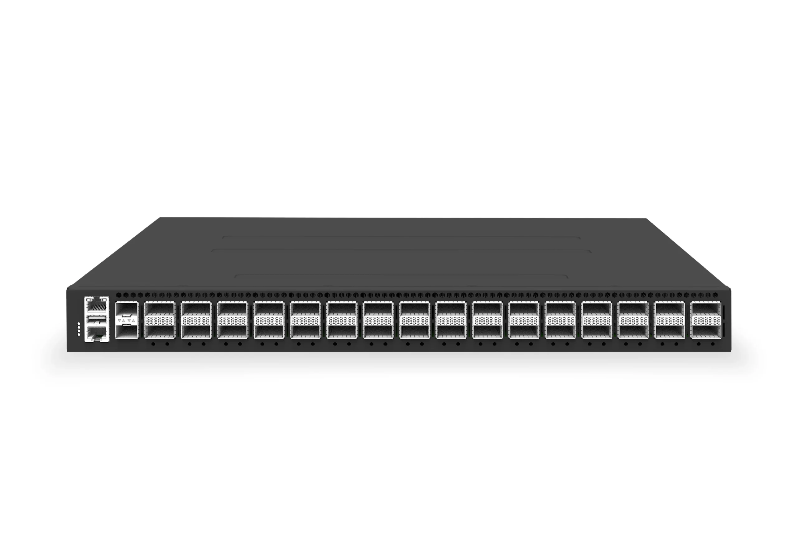 datacenter aiXS-DC-32X400-SP-G232-port 400G spine/core switch for high-capacity data center fabrics and AI-ready backbones.View product
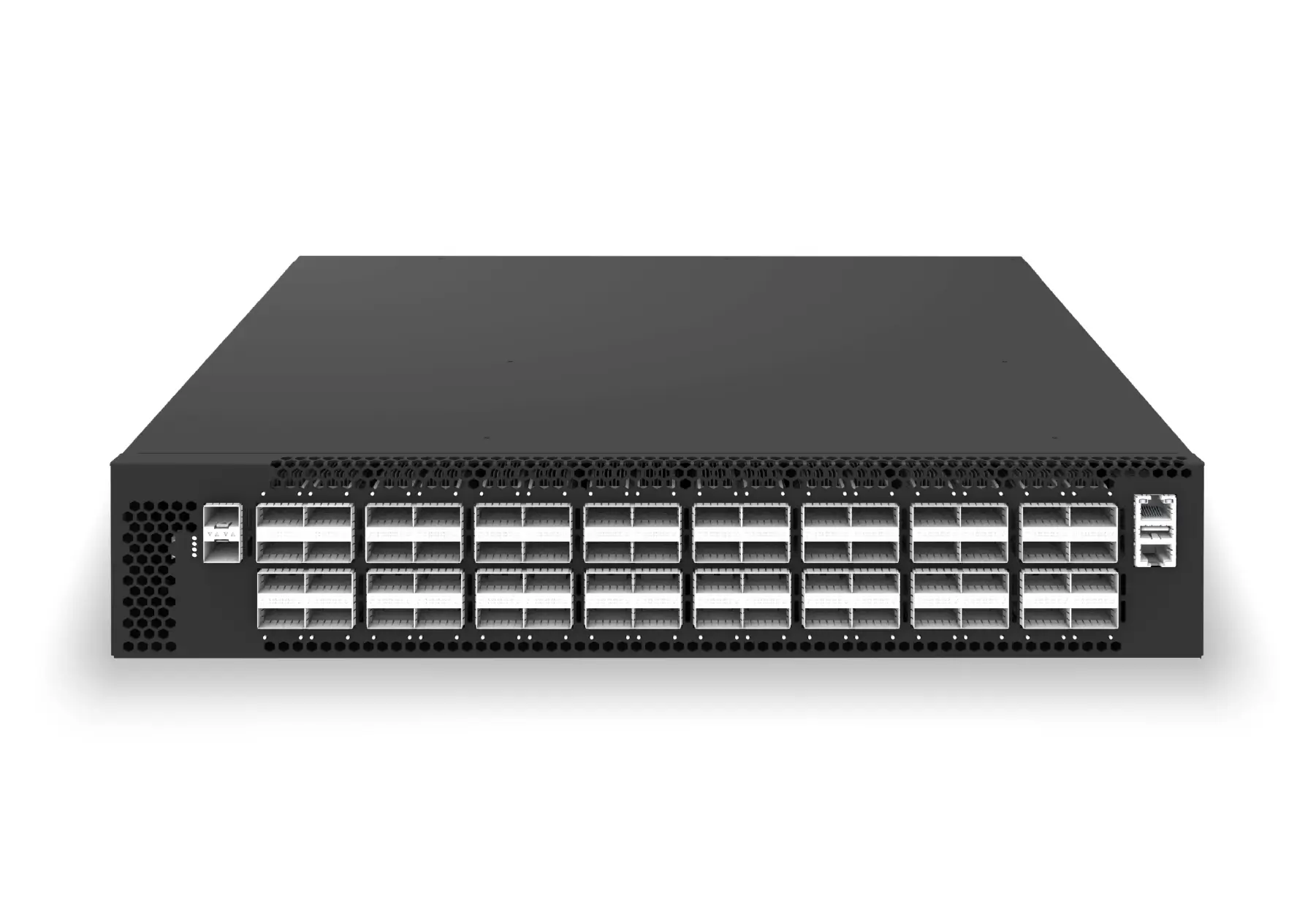 datacenter aiXS-DC-64X200-LS-G164-port 200G leaf/spine switch for high-bandwidth storage, compute, and scale-out data center fabrics.View product
Continue reading
Related articles
 Technical ArticleDCBX, PFC, ECN, and Fast CNP: Building Lossless Ethernet for AI Training FabricsEngineering guidance on DCBX, PFC, ECN, and Fast CNP for Australian AI fabric teams building lossless Ethernet for RoCE v2 training clusters.Read article
 Technical ArticleWhat AI Data Center Ethernet Demands Mean for SONiC Network Operators in AustraliaEngineering guide for Australian SONiC operators running AI Ethernet fabrics, covering RoCE, 400G/800G links, telemetry, failures, optics, and support.Read article
 Technical ArticleWhat AI Fabric Ethernet Switching Actually Requires -- and Where SONiC Fits in the StackA practical engineering guide to AI fabric Ethernet switching requirements, explaining where SONiC fits across RoCE v2, PFC, ECN, DCBX, telemetry, and 400G/800G operations.Read article