In brief
Engineering guidance on DCBX, PFC, ECN, and Fast CNP for Australian AI fabric teams building lossless Ethernet for RoCE v2 training clusters.
Key takeaways
- Large language model training, distributed deep learning, and high-performance computing clusters push east-west traffic volumes far beyond what traditional data center networks were designed to handle.
- The result is that AI fabric builders need lossless Ethernet -- a network state where switches never drop frames under normal congestion conditions.
- Data Center Bridging Capability Exchange Protocol (DCBX) is the handshake mechanism that allows adjacent network devices -- switch-to-switch and switch-to-NIC -- to advertise and agree on DCB parameters before data traffic flows.
Why AI Training Demands Lossless Ethernet
Large language model training, distributed deep learning, and high-performance computing clusters push east-west traffic volumes far beyond what traditional data center networks were designed to handle. When a single GPU node generates tens of gigabits per second of RDMA over Converged Ethernet v2 (RoCE v2) traffic across hundreds of endpoints, even a small amount of packet loss can cause dramatic throughput collapse. Unlike TCP-based applications that tolerate retransmissions gracefully, RoCE v2 relies on RDMA semantics where a dropped packet can stall an entire queue pair and ripple across synchronized training steps.
The result is that AI fabric builders need lossless Ethernet — a network state where switches never drop frames under normal congestion conditions. Achieving this requires a coordinated set of Data Center Bridging (DCB) features: DCBX for capability negotiation, PFC for per-priority pause signaling, ECN for congestion marking, and Fast CNP for rapid congestion response at the NIC level. Each protocol solves a different piece of the puzzle, and misconfiguring any one of them can reintroduce the packet loss they are meant to prevent.
DCBX: Negotiating Lossless Capabilities Between Switches and NICs
Data Center Bridging Capability Exchange Protocol (DCBX) is the handshake mechanism that allows adjacent network devices — switch-to-switch and switch-to-NIC — to advertise and agree on DCB parameters before data traffic flows. Defined as part of the IEEE 802.1Qaz standard, DCBX uses LLDP (Link Layer Discovery Protocol) Type-Length-Value (TLV) exchanges to negotiate three key capabilities:
- Priority Flow Control (PFC) parameters: Which traffic classes support pause, and on which priorities.
- Enhanced Transmission Selection (ETS) bandwidth allocation: How much bandwidth each traffic class receives.
- Application Protocol TLVs: Which application types (e.g., FCoE, iSCSI, RoCE) map to which priorities.
In an AI fabric, DCBX ensures that every link in the spine-leaf topology agrees on which 802.1p priority carries RoCE v2 traffic, that PFC is enabled on that priority, and that bandwidth allocations prevent starvation of management or storage traffic. Without DCBX, an operator would need to manually configure matching PFC and ETS settings on every switch port and every NIC — a process that becomes error-prone at scale.
PFC: Per-Priority Pause for Lossless Forwarding
Priority Flow Control (PFC), defined by IEEE 802.1Qbb, allows a switch or NIC to pause traffic for a specific 802.1p priority without stopping all traffic on the link. That distinction is critical. Classic Ethernet pause can create broad head-of-line blocking; PFC is meant to protect only the lossless traffic class, usually the priority carrying RoCE v2.
In a GPU training fabric, PFC should be treated as a safety mechanism, not the primary congestion-control method. If PFC counters climb constantly during normal workload, the fabric is already too close to congestion. The preferred behaviour is:
- PFC is enabled only on the RoCE priority, not globally across all 8 priorities.
- XOFF and XON thresholds are tuned to the switch buffer architecture and line rate.
- ECN marks traffic before PFC thresholds are reached.
- PFC deadlock detection and recovery are enabled where supported.
- Pause counters are monitored per priority, per port, and per time window.
For 400G and 800G links, buffer headroom disappears quickly. A design that survives at 100G may fail when the same fan-in pattern moves to 400G because each microburst fills queues faster. This is why PFC threshold values should be validated with realistic traffic rather than copied from another platform.
ECN: Congestion Notification Without Frame Drops
Explicit Congestion Notification (ECN), specified in RFC 3168, allows the switch to mark congestion before frames are dropped. In RoCE v2 environments, ECN marks are reflected back to senders through congestion notification behaviour so that transmit rates can be reduced before PFC pause frames become necessary.
The engineering rule is simple: ECN must fire early enough to prevent PFC from becoming the normal operating state. If ECN thresholds are set too high, congestion reaches the PFC XOFF threshold before senders slow down. If thresholds are set too low, the fabric may throttle aggressively and leave usable bandwidth on the table.
Australian teams evaluating AI fabric Ethernet should ask vendors to document the ECN configuration model in the proposed SONiC image:
- Which queues and priorities are ECN-enabled?
- What are the minimum and maximum ECN marking thresholds?
- Are thresholds static, dynamic, or tied to a shared-buffer profile?
- Can ECN-marked packet counts be exported through telemetry?
- How are ECN, PFC, and buffer counters correlated during incident review?
Fast CNP: Accelerating the Congestion Response Loop
Fast Congestion Notification Packet (Fast CNP) is an optimization designed to reduce the latency of the ECN congestion response loop in RoCE v2 networks. In standard ECN/CNP operation, there is an inherent delay: the switch marks a packet, the receiver processes it, generates a CNP, and sends it back to the sender. For high-bandwidth AI training traffic running at 100G, 200G, 400G, or 800G per port, this delay can allow significant additional data to enter the fabric before the sender reacts.
Fast CNP addresses this by shortening the feedback path:
- Switch-side behaviour: Some implementations can trigger congestion feedback more directly or mark consecutive packets more aggressively under sustained congestion.
- NIC-side behaviour: Fast CNP-capable NICs can process ECN markings with lower latency and apply rate reduction sooner.
- System effect: The feedback loop can converge closer to a single round-trip event, reducing the time during which queues continue to fill.
Fast CNP is particularly important in multi-tenant AI fabrics where many GPU jobs run simultaneously. More concurrent flows mean more burst alignment, and burst alignment is where lossless Ethernet designs either prove themselves or expose tuning mistakes.
Practical Design Checklist for a Spine-Leaf AI Training Fabric
Building a reliable lossless AI fabric requires configuring DCBX, PFC, ECN, and Fast CNP as a coordinated system, not as independent features. A practical design checklist should include:
Step 1: Define the priority design.
- Assign RoCE v2 traffic to a dedicated 802.1p priority (commonly priority 3 or 4).
- Assign storage traffic (iSCSI or NVMe-oF) to a separate priority if applicable.
- Leave management and TCP traffic on the default best-effort priority.
Step 2: Enable DCBX on all fabric links.
- Verify that DCBX TLV exchanges succeed between every switch-to-switch and switch-to-NIC link.
- Confirm that PFC and ETS parameters match across all devices.
Step 3: Configure PFC on the RoCE priority.
- Set XOFF and XON thresholds appropriate for the switch buffer architecture.
- Enable PFC only on the designated lossless priority; do not enable PFC on all priorities.
- Configure PFC deadlock detection and recovery if the platform supports it.
Step 4: Configure ECN marking thresholds.
- Set the ECN marking threshold below the PFC XOFF threshold (e.g., ECN at 50% buffer, PFC at 65%).
- Enable ECN marking on the RoCE priority queue at all leaf and spine switches.
Step 5: Enable Fast CNP on NICs and switches.
- Update NIC firmware to a version that supports Fast CNP.
- Enable any switch-side Fast CNP or enhanced marking features available on the platform.
- Validate that the congestion feedback loop converges within acceptable latency for the training workload.
Step 6: Test with realistic traffic.
- Use tools like
ib_write_bw,perftest, or vendor-specific traffic generators to simulate AI training traffic patterns. - Monitor PFC pause frame counters, ECN-marked packet counts, and CNP rates during load testing.
- Verify that PFC pause rates remain low (indicating ECN is doing most of the work) and that no frame drops occur under peak load.
Failure Modes and Rework Criteria
Even with all four protocols enabled, lossless fabrics can fail if the configuration is not tuned to the specific traffic patterns and hardware. The most common failure modes include:
1. PFC Storms / Congestion Spreading. A single congested port can propagate pause frames across the fabric, stalling traffic on unrelated paths. Mitigation: proper ECN thresholds so congestion is resolved end-to-end before PFC propagates, and buffer monitoring to detect hotspots early.
2. PFC Deadlock. In rare cases, circular PFC pause dependencies can cause a permanent stall where two switch ports are paused waiting for each other. Mitigation: enable PFC deadlock detection and timeout recovery features on switches that support them.
3. Priority Misalignment. If a leaf switch is configured for PFC on priority 3 but a connected NIC is using priority 4 for RoCE v2, the NIC will not respond to PFC pause frames and frames may be dropped silently. Mitigation: enforce DCBX negotiation and validate with packet captures during commissioning.
4. ECN Threshold Set Too High. If the ECN marking threshold is set near the PFC XOFF threshold, ECN cannot signal congestion in time, and PFC triggers unnecessarily. This defeats the purpose of ECN and increases latency.
5. Insufficient Buffer Depth. At 400G line rates, micro-bursts can fill shallow buffers in microseconds. If switch buffer sizes are insufficient for the number of concurrent high-bandwidth flows, even correctly configured PFC and ECN cannot prevent drops. Mitigation: choose switches with adequate per-port and shared buffer sizes, and plan for worst-case fan-in ratios at leaf switches.
Lossless Ethernet Acceptance Matrix
| Control Plane or Data Plane Area | Evidence to Capture | Acceptance Target | Rework Trigger |
|---|---|---|---|
| DCBX negotiation | LLDP/DCBX TLVs from switch-to-NIC and switch-to-switch links | RoCE priority, ETS, and PFC settings match across all tested links after 3 reload cycles | Any endpoint negotiates a different priority or loses DCBX state after reload |
| PFC behaviour | Per-priority pause counters, deadlock recovery status, queue occupancy | PFC appears as a rare safety event during 24-48 hours of test traffic, not as continuous congestion control | PFC frames propagate across unrelated classes or remain high during steady-state workload |
| ECN marking | ECN-marked packet counters, buffer thresholds, CNP correlation | ECN marks before PFC XOFF, and senders reduce rate before frame drops occur | ECN counters stay flat while PFC rises, or thresholds are undocumented |
| Fast CNP response | NIC firmware version, CNP counters, convergence notes, traffic replay | Congestion feedback converges quickly enough to protect 100G/400G/800G lossless queues | Vendor cannot expose CNP evidence or explain sender reaction behaviour |
| Operations readiness | Telemetry export, alert thresholds, rollback commands, incident runbook | Operators can identify congested queue, port, priority, and time window without packet guesswork | Troubleshooting depends on manual console inspection after the event |
Putting It All Together: A Layered Lossless Fabric Design
xSONiC data center AI switches are designed for spine-leaf fabric deployments serving AI and HPC workloads. Key capabilities relevant to lossless Ethernet include:
- Enterprise SONiC-based NOS: Open-source networking operating system with DCB feature support including DCBX, PFC, and ECN configuration via CLI, NETCONF/YANG, or AIDC Controller.
- 100G / 400G / 800G port options: High-density switching for GPU backend fabrics where per-node bandwidth requirements are scaling from 100G to 400G and beyond.
- RoCE v2 optimized: Switches designed with the buffer architectures and congestion management features needed for RDMA workloads.
For AI infrastructure builders evaluating open networking options, xSONiC provides an alternative to closed-vendor stacks with the flexibility to tune DCB parameters at the NOS level rather than relying on vendor-specific GUIs or hidden defaults.
Engineering FAQ
Should PFC be enabled on every priority? No. PFC should be limited to the traffic class that truly requires lossless behaviour, typically the RoCE v2 priority. Enabling PFC everywhere increases the chance of head-of-line blocking and congestion spreading.
What should be lower: ECN threshold or PFC XOFF threshold? ECN should mark before PFC XOFF is reached. The exact buffer values depend on ASIC, line rate, NIC behaviour, and workload, but the design intent is that ECN handles congestion before PFC becomes necessary.
How do Australian buyers validate vendor claims about lossless Ethernet? Require a pilot with realistic traffic, representative optics, the quoted SONiC image, NIC firmware notes, PFC/ECN/CNP counters, link failure tests, and a written rework threshold. Feature checklists are not enough.
Where does xSONiC fit in the lossless fabric stack? xSONiC should be evaluated as the switch and open NOS layer in a broader RoCE v2 system. The acceptance decision should include switch ASIC behaviour, SONiC configuration, optics, NIC settings, telemetry, and support workflow.
Related xSONiC Resources
Sources Reviewed
- Ethernet Network Adapters - ConnectX NICs | NVIDIA
- NVIDIA BlueField Data Processing Unit
- NVIDIA Spectrum-X Ethernet Platform
- IEEE 802.1Qbb Priority Flow Control
- IEEE 802.1Qaz Enhanced Transmission Selection and DCBX
- RFC 3168 Explicit Congestion Notification
- IETF Fast CNP Draft
- Ultra Ethernet Consortium
- OpenConfig gNMI Specification
- OpenConfig
- RFC 7950 - The YANG 1.1 Data Modeling Language
- RFC 6241 - Network Configuration Protocol (NETCONF)
- SONiC Project Documentation
- Broadcom Ethernet Switching
- Marvell Switching
- NVIDIA Ethernet Switching
- Open Compute Networking
- SONiC GitHub
- SONiC Foundation
Product fit
Products referenced for evaluation
These products are referenced for evaluation context in the article. Confirm workload, port, optics, software, interoperability, and support requirements against the exact deployment before procurement.
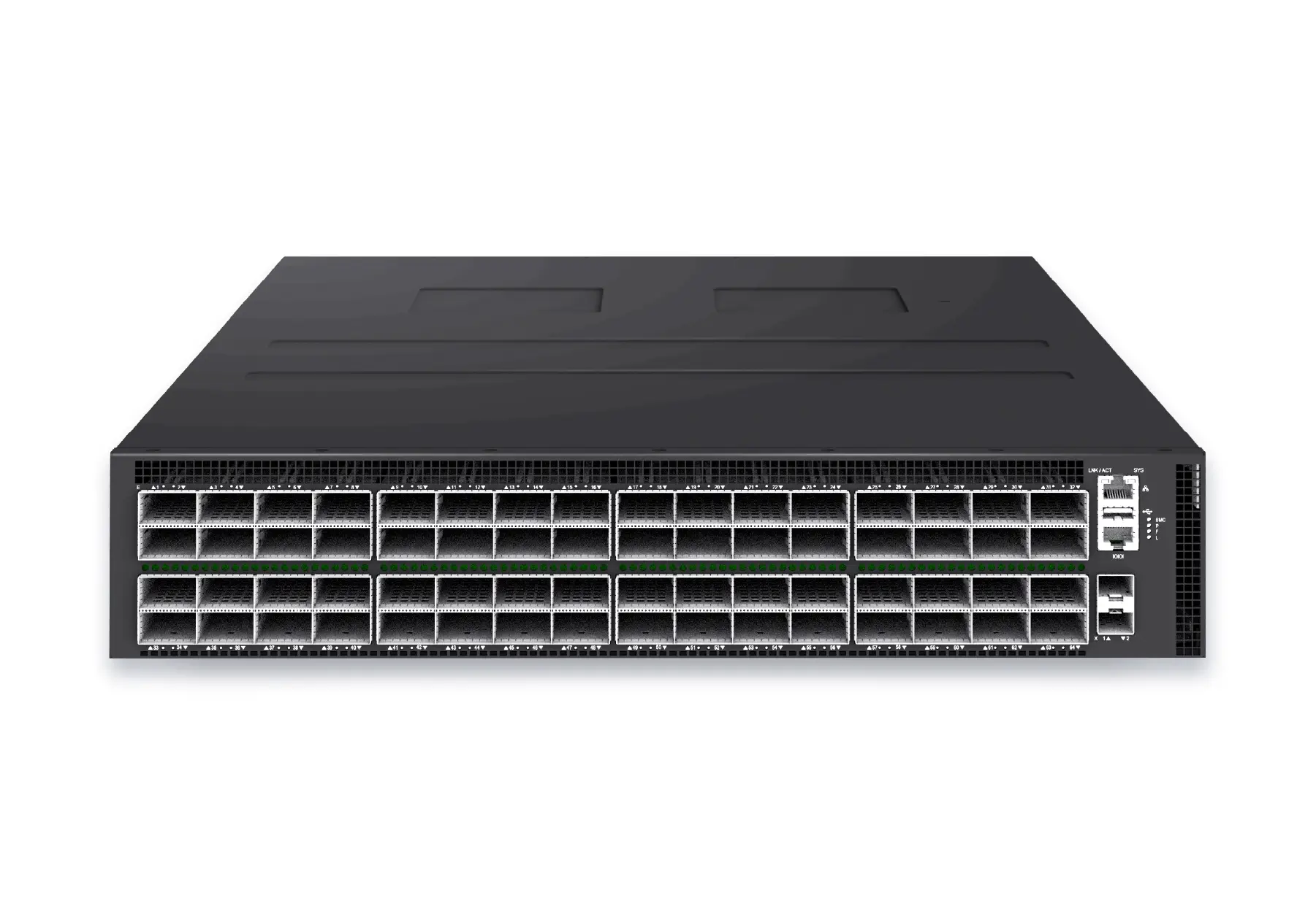 datacenter aiXS-DC-64X800-AI-G164-port 800G AI fabric switch for large-scale GPU clusters, HPC backbones, and ultra-high-throughput data center networks.View product
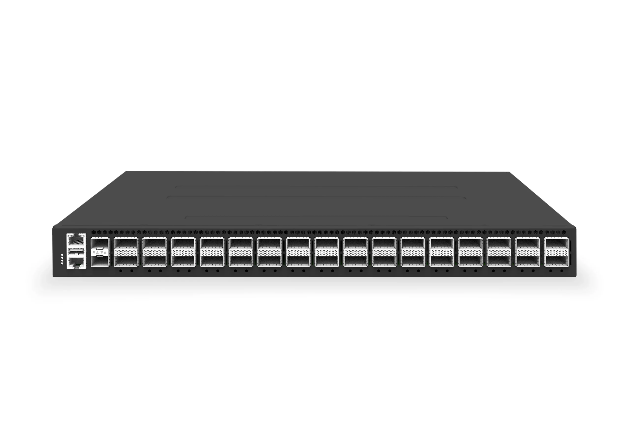 datacenter aiXS-DC-32X400-SP-G232-port 400G spine/core switch for high-capacity data center fabrics and AI-ready backbones.View product
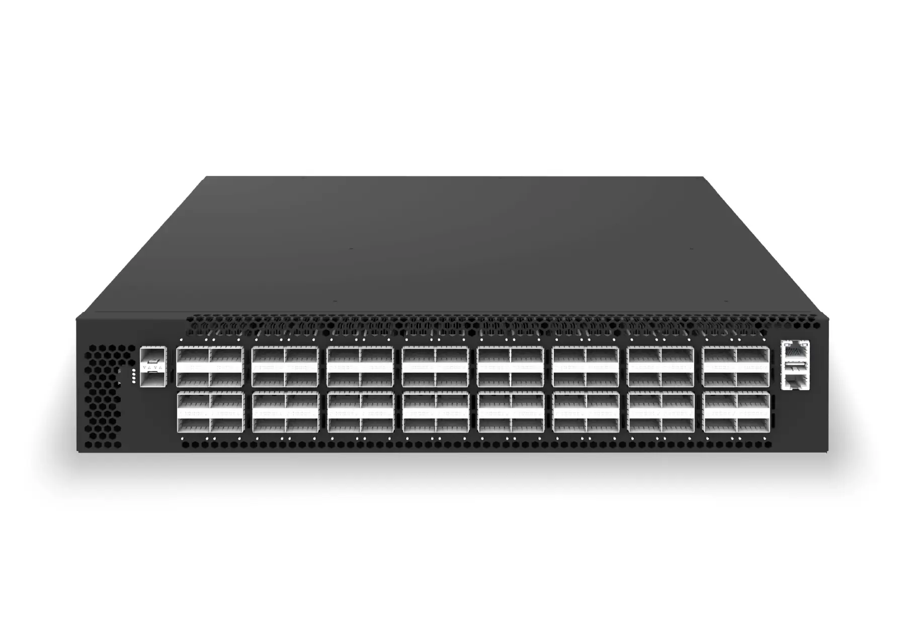 datacenter aiXS-DC-64X200-LS-G164-port 200G leaf/spine switch for high-bandwidth storage, compute, and scale-out data center fabrics.View product
Continue reading
Related articles
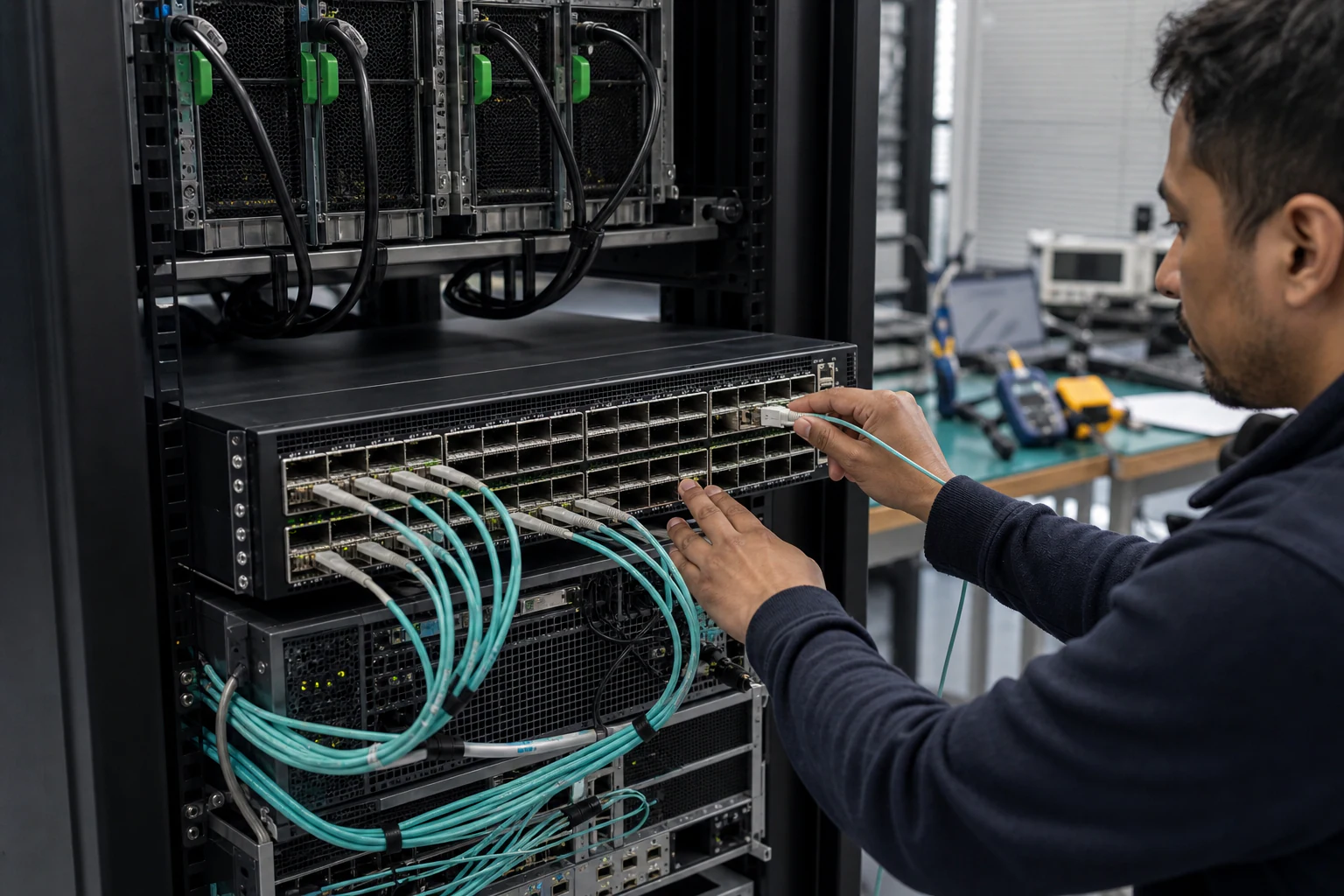 Technical ArticleWhat AI Data Center Ethernet Demands Mean for SONiC Network Operators in AustraliaEngineering guide for Australian SONiC operators running AI Ethernet fabrics, covering RoCE, 400G/800G links, telemetry, failures, optics, and support.Read article
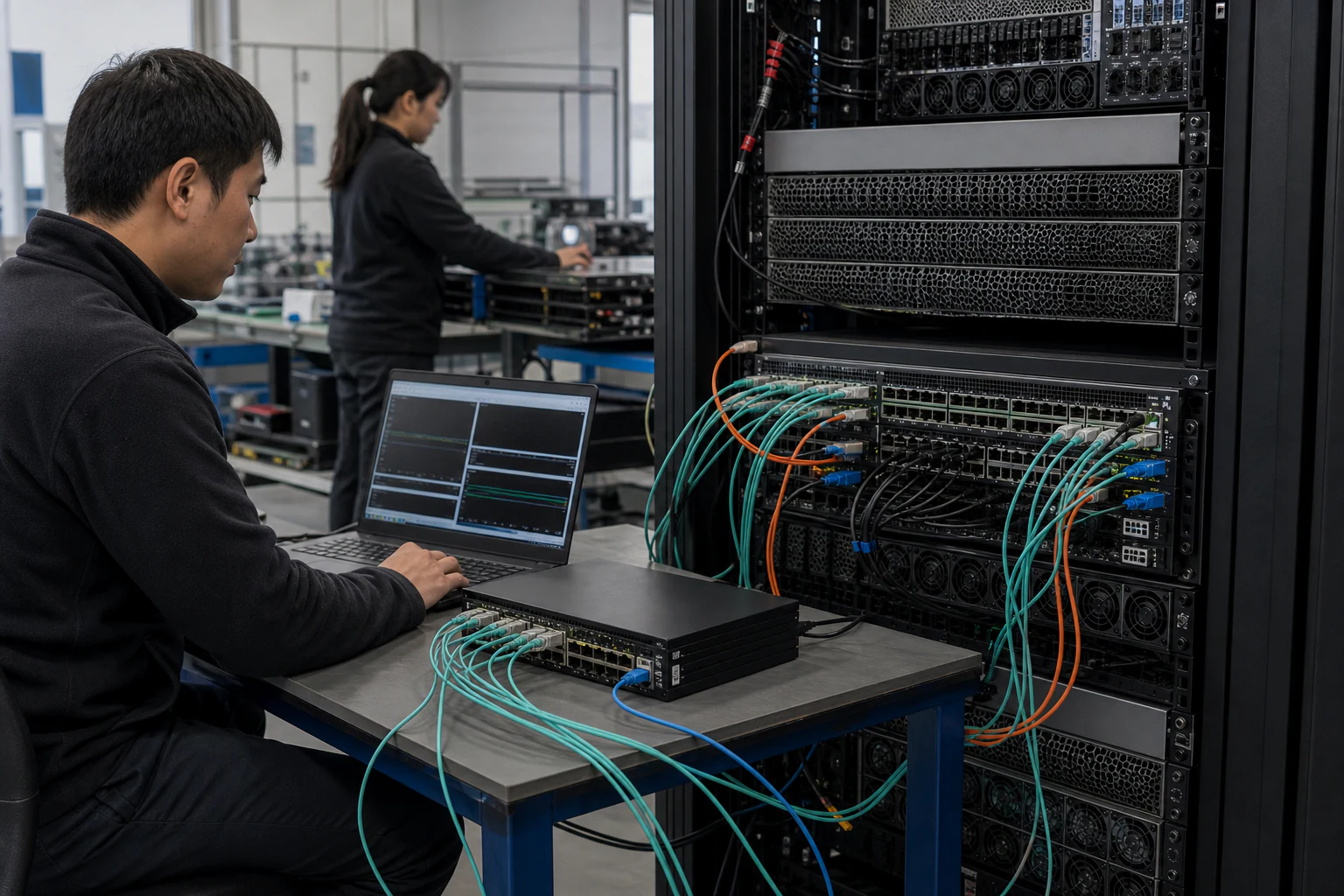 Technical ArticleWhat AI Fabric Ethernet Switching Actually Requires -- and Where SONiC Fits in the StackA practical engineering guide to AI fabric Ethernet switching requirements, explaining where SONiC fits across RoCE v2, PFC, ECN, DCBX, telemetry, and 400G/800G operations.Read article
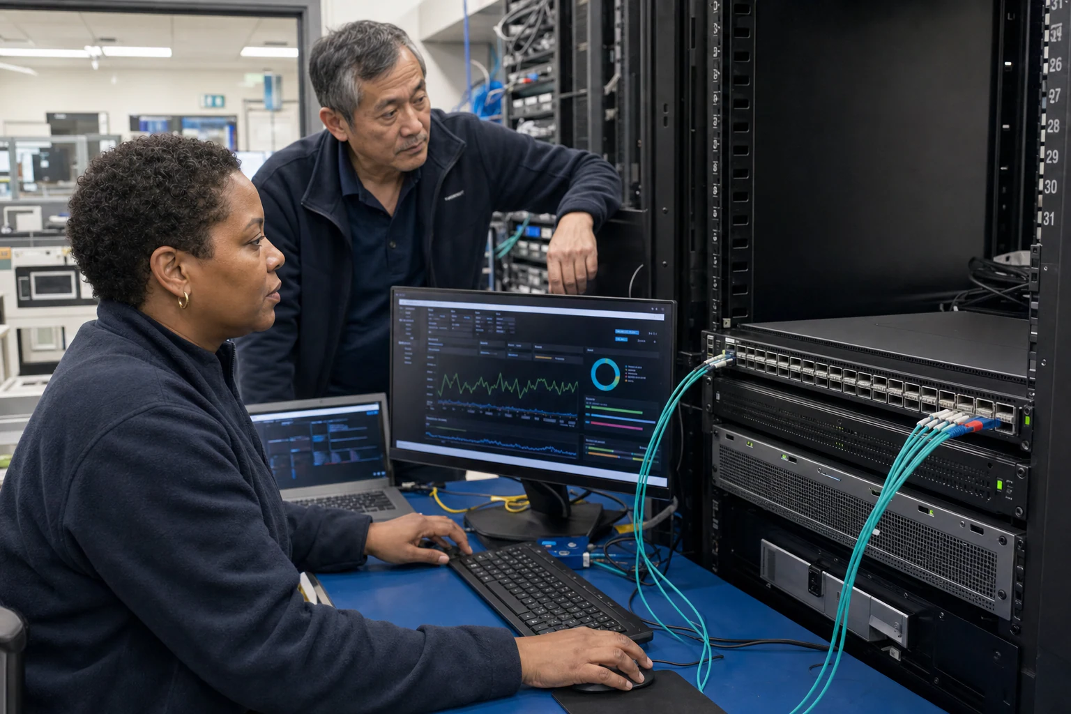 Technical ArticleWhy Your AI Fabric Needs a Centralized Controller, Not CLI-Based Hop ManagementGuide to centralized AI fabric control for SONiC environments, covering RoCE consistency, telemetry, automation, and operational risk.Read article