In brief
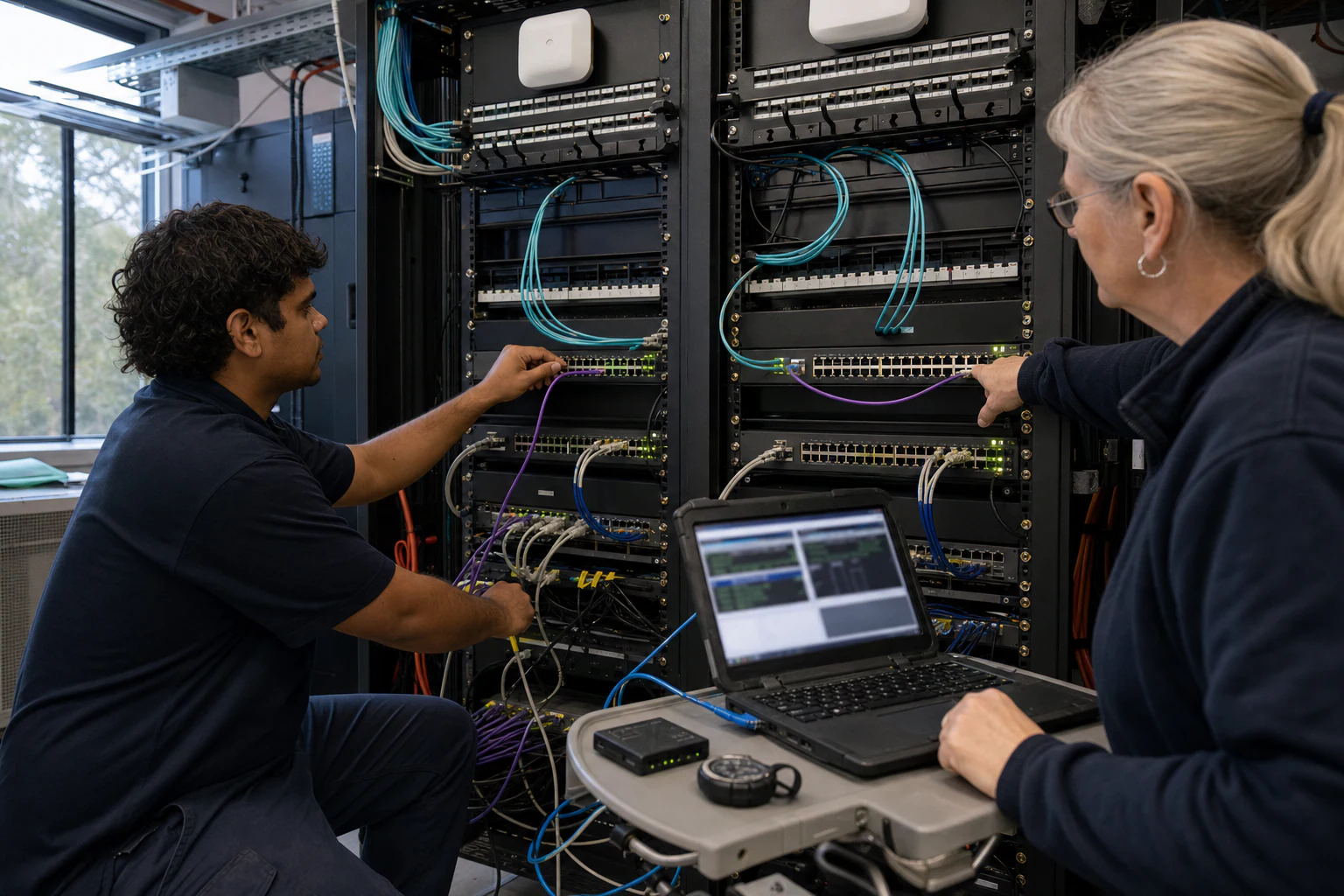
Practical lab test plan for campus virtual chassis and cluster designs on open SONiC switches, covering failover, PoE, telemetry, and support.
Key takeaways
- Australian enterprise campus networks are at a turning point. The combination of sovereign data requirements, growing AI-driven edge workloads, and the push toward open networking stacks means that managed service providers and integrators can no longer treat campus switch selection as a simple box-ticking exercise.
- This is where a structured lab test plan becomes essential. Before deploying virtual chassis or cluster topologies across an Australian enterprise campus, MSPs and integrators need a controlled environment to validate failover behaviour, PoE continuity, traffic convergence, and management-plane stability.
- The Australian market adds its own pressure. The OCP Podcast's conversation with David Hirst, CEO of Macquarie Data Centres, highlighted how Australia's sovereign approach to data infrastructure, unique regulatory environment, and geographically distributed enterprise footprint shape infrastructure decisions differently from US or European deployments.
Why Australian MSPs Need a Virtual Chassis Lab Test Plan
Australian enterprise campus networks are at a turning point. The combination of sovereign data requirements, growing AI-driven edge workloads, and the push toward open networking stacks means that managed service providers and integrators can no longer treat campus switch selection as a simple box-ticking exercise. Virtual chassis and cluster configurations — where multiple physical switches operate as a single logical device — promise simplified management, higher availability, and flatter topologies. But the promises only hold if the configuration actually works under production-like stress.
This is where a structured lab test plan becomes essential. Before deploying virtual chassis or cluster topologies across an Australian enterprise campus, MSPs and integrators need a controlled environment to validate failover behaviour, PoE continuity, traffic convergence, and management-plane stability. SONiC (Software for Open Networking in the Cloud) is an open-source network operating system that runs on switches from multiple vendors and ASICs, offering a full suite of network functionality including BGP and RDMA. Its modular, container-based architecture makes it a strong candidate for campus access and aggregation roles, but any open NOS introduces integration variables that closed-stack vendors hide behind their own QA walls. A lab test plan puts that QA back in the hands of the integrator.
The Australian market adds its own pressure. The OCP Podcast’s conversation with David Hirst, CEO of Macquarie Data Centres, highlighted how Australia’s sovereign approach to data infrastructure, unique regulatory environment, and geographically distributed enterprise footprint shape infrastructure decisions differently from US or European deployments. MSPs serving Australian government, healthcare, education, and resources-sector clients must account for compliance frameworks, limited on-site engineering availability at remote sites, and carrier interdependencies that differ from other markets.
Setting Up the Lab Environment
A virtual chassis lab does not need to replicate an entire campus, but it must capture the critical failure domains. The following baseline setup is recommended for an initial test cycle:
Minimum hardware:
- 3 to 4 access-layer switches of the target model in virtual chassis or cluster formation (to simulate a typical floor closet or IDF stack)
- 1 aggregation or distribution switch (to test uplink failover and MC-LAG peering)
- At least 1 multi-gigabit or PoE-capable member switch if the deployment includes Wi-Fi 6E or Wi-Fi 7 access points
- A traffic generator (hardware appliance or software-based, such as TRex or Ostinato) connected to at least 2 member ports
- A management workstation running the chosen NOS management tools, NETCONF/YANG clients, and SNMP monitoring
Firmware and image baseline: All switches should run the same SONiC image version. SONiC’s container-based architecture means each network function runs in its own Docker container, which provides better fault isolation and simplified upgrades. However, in a virtual chassis context, firmware homogeneity across members is critical. Record the exact image hash, build date, and container versions before beginning any test. If the target platform supports Enterprise SONiC distribution features specific to virtual chassis (such as a dedicated control-plane interconnect or stacking fabric), confirm the feature availability with the hardware vendor or xSONiC product team.
Network topology: Connect the virtual chassis members using the recommended stacking or inter-chassis links. Connect the aggregation switch via dual uplinks from two different chassis members to enable MC-LAG or multi-homing validation. Attach the traffic generator to ports on at least two different member switches so that cross-member forwarding can be tested.
Phase 1 — Chassis Formation and Boot Sequence Validation
The first test phase validates the most basic promise of virtual chassis: that multiple physical switches boot, elect roles, and present as a single managed entity.
Test cases:
-
Cold boot formation: Power on all member switches simultaneously. Measure time from power-on to the point where the virtual chassis is fully formed and the management plane is reachable. Record which member is elected primary (master) and which becomes secondary (backup).
-
Sequential boot: Power on members one at a time with a 30-second delay. Verify that late-joining members are correctly recognized, assigned roles, and synchronized with the running configuration.
-
Role preemption: If the platform supports role priority configuration, set a non-default priority on a specific member and reboot the chassis. Verify the designated member assumes the primary role.
-
Split-brain detection: Disconnect the stacking or control-plane interconnect between members while all are running. Verify that the system detects the split condition and takes a defined action (for example, shutting down one partition or disabling forwarding on the secondary partition) rather than allowing two independent forwarding planes to operate with conflicting identities.
Pass criteria: The chassis forms predictably, role election is deterministic, and split-brain recovery follows a documented and safe behaviour. Any ambiguity here is a deployment blocker.
Phase 2 — Failover and Resiliency Testing
This is the most critical phase for MSPs who will be managing these deployments remotely or at sites with limited on-site technical staff.
Test cases:
-
Active supervisor failover: With traffic flowing through the chassis, abruptly remove power from the primary member (or disable its stacking link). Measure traffic loss duration, control-plane convergence time, and whether the backup member assumes full forwarding and management responsibility within an acceptable window.
-
Link failure on a non-primary member: Disconnect a downlink port on a member switch that is actively carrying traffic. Verify that the remaining members and the chassis as a whole continue to operate without disruption.
-
Uplink failover with MC-LAG: If the deployment uses MC-LAG to the aggregation layer, simulate the failure of one uplink member. The OCP Networking project’s scope includes SONiC as a sub-project alongside SAI (Switch Abstraction Interface) and ONIE, which together enable the disaggregated networking stack that makes features like MC-LAG portable across hardware vendors. Verify that traffic re-routes to the surviving uplink within the expected convergence window.
-
ISSU (In-Service Software Upgrade): If the platform supports rolling firmware upgrades across chassis members without full downtime, test the upgrade path from the current image to the target image. Verify that traffic forwarding continues (possibly at reduced bandwidth) throughout the process.
Pass criteria: Failover times must meet the deployment’s SLA requirements. For campus environments, sub-second to low-single-digit-second failover is typically expected for Layer 2 forwarding. Routing protocol convergence (BGP, OSPF) may take longer and should be measured separately. If failover produces a management-plane outage exceeding 60 seconds, that is a significant concern for remote-managed sites.
Phase 3 — PoE and Endpoint Behaviour in Stacked Mode
Campus virtual chassis deployments almost always carry PoE endpoints: access points, IP cameras, VoIP phones, and IoT devices. A virtual chassis that forwards traffic correctly but drops PoE during member failover is not production-ready.
Test cases:
-
PoE budget per member: Connect PoE loads (or PoE load simulators) to multiple ports on each member. Verify that the per-member and per-chassis PoE budgets are correctly calculated and enforced.
-
PoE during member failover: With PoE devices powered from the secondary member, trigger a primary-member failover. Verify that PoE delivery to endpoints on the secondary member is uninterrupted.
-
LLDP-MED negotiation: Connect a Wi-Fi access point (preferably Wi-Fi 6E or Wi-Fi 7) and verify that LLDP-MED correctly negotiates power class and that the AP receives the expected wattage. If the campus deployment includes xSONiC access points alongside the switches, test the end-to-end PoE and LLDP-MED behaviour of the combined stack.
-
PoE scheduling and priority: If the NOS supports PoE port priority or time-based PoE scheduling, verify these features work correctly in virtual chassis mode and are preserved across failover events.
Pass criteria: PoE delivery must be continuous during any single-member failure. LLDP-MED negotiation must complete within the AP’s boot window. Any PoE reset during failover will cause endpoint reboots, which is unacceptable for production campus deployments.
Phase 4 — Management Plane, Telemetry, and Policy Validation
For Australian MSPs managing multiple customer sites, the management plane is as important as the data plane.
Test cases:
-
Single IP management: Verify that the virtual chassis is reachable via a single management IP address and that all member-level diagnostics are accessible through that IP.
-
NETCONF/YANG and SNMP: If the deployment uses NETCONF for configuration management, verify that YANG models correctly reflect the virtual chassis topology (member count, role, port mapping). Test configuration pushes (VLAN creation, port assignment, ACL application) and verify they propagate to all members. SONiC supports programmatic configuration methods alongside CLI, and the OCP ecosystem emphasizes standard interfaces for automation.
-
Telemetry streaming: If the deployment uses streaming telemetry (gNMI, sFlow, or SNMP traps), verify that telemetry data includes per-member granularity and that the chassis-level aggregation does not obscure per-port or per-member anomalies.
-
RBAC and audit logging: In Australian government and regulated-sector deployments, role-based access control and audit trail completeness are non-negotiable. Verify that administrative actions on the virtual chassis are logged with sufficient detail for compliance audits.
-
Policy-based routing (PBR) and ACL consistency: Apply PBR rules and ACLs at the chassis level. Verify they are enforced consistently on all member switches, including during failover events.
Phase 5 — Scale and Stress Testing
Lab tests that only validate happy-path behaviour miss the failures that matter most in production.
Test cases:
-
MAC address table scale: Populate the MAC address table near its documented limit across all members. Verify that the chassis does not experience forwarding instability or excessive control-plane CPU utilization.
-
ARP/ND table scale: Similarly, stress the ARP and neighbour discovery tables. Campus networks with large VLANs and IoT device populations can generate high ARP churn.
-
Broadcast storm containment: Inject broadcast traffic at a controlled rate from the traffic generator. Verify that the virtual chassis correctly contains broadcast domains and does not allow a storm on one member to degrade forwarding on other members.
-
Concurrent failure simulation: Trigger two failures simultaneously — for example, a member power loss plus an uplink failure. This tests whether the chassis’s resilience mechanisms are independent or whether they interact in unexpected ways.
-
Long-duration soak test: Run the chassis under moderate traffic load for at least 48 to 72 hours with no manual intervention. Monitor for memory leaks, CPU creep, control-plane instability, or silent forwarding failures. This is particularly important for open NOS platforms where containerized processes may exhibit different resource profiles over time.
Pass criteria: No forwarding failures, no uncontrolled restarts, and no degradation that exceeds the documented platform limits.
Campus Cluster Lab Acceptance Matrix
| Test area | Evidence to capture | Acceptance gate | Rework trigger |
|---|---|---|---|
| Cluster formation | Member discovery, role election, config sync, image version, and reboot order | 3 clean formation cycles with no split-brain condition | Cluster state differs after reboot or member replacement |
| Failure recovery | Uplink loss, member loss, control-plane restart, and management-plane isolation | Traffic impact, convergence, and operator actions recorded for 5 failures | The lab proves steady state but not failure state |
| Endpoint services | PoE draw, 802.1X, voice VLAN, camera traffic, multicast, and LLDP-MED | 48 ports under mixed endpoint load for 24 hours | Endpoint behaviour is tested only with laptops |
| Operations | Telemetry, logs, backup, restore, upgrade, rollback, and support evidence | Evidence bundle can be produced within 2 hours of a simulated incident | Operations cannot explain which node owned the fault |
| Scale decision | Access count, aggregation uplinks, oversubscription, spare capacity, and rollout wave | 30 days pilot plan approved before multi-site rollout | Procurement approves the topology before lab failure data exists |
Engineering FAQ
What should be validated before a Wi-Fi 6E or Wi-Fi 7 rollout? Validate channel plan, 6 GHz client readiness, PoE budget, uplink capacity, roaming, authentication, RF density, interference, and management tooling. The AP standard alone does not prove campus performance.
Why does backhaul planning matter for modern access points? Wi-Fi 6E and Wi-Fi 7 can expose bottlenecks in access switching, PoE, cabling, and uplink design. Buyers should confirm whether 2.5G, 5G, 10G, and PoE budgets match the real AP deployment plan.
What evidence should vendors provide for enterprise WLAN projects? Ask for supported security modes, firmware lifecycle, controller or cloud management model, RF planning assumptions, client compatibility notes, and a pilot report from a representative building or floor.
Related xSONiC Resources
Sources Reviewed
- IEEE 802.1Q Bridges and Bridged Networks
- IEEE 802.1AX Link Aggregation
- Ethernet Network Adapters - ConnectX NICs | NVIDIA
- NVIDIA BlueField Data Processing Unit
- NVIDIA Spectrum-X Ethernet Platform
- OpenConfig gNMI Specification
- OpenConfig
- RFC 7950 - The YANG 1.1 Data Modeling Language
- RFC 6241 - Network Configuration Protocol (NETCONF)
- IEEE 802.11be Wireless LAN Standard
- IEEE 802.3bt Power over Ethernet
- SONiC Project Documentation
- Broadcom Ethernet Switching
- Marvell Switching
- NVIDIA Ethernet Switching
- Open Compute Networking
- SONiC GitHub
- SONiC Foundation
Product fit
Products referenced for evaluation
These products are referenced for evaluation context in the article. Confirm workload, port, optics, software, interoperability, and support requirements against the exact deployment before procurement.
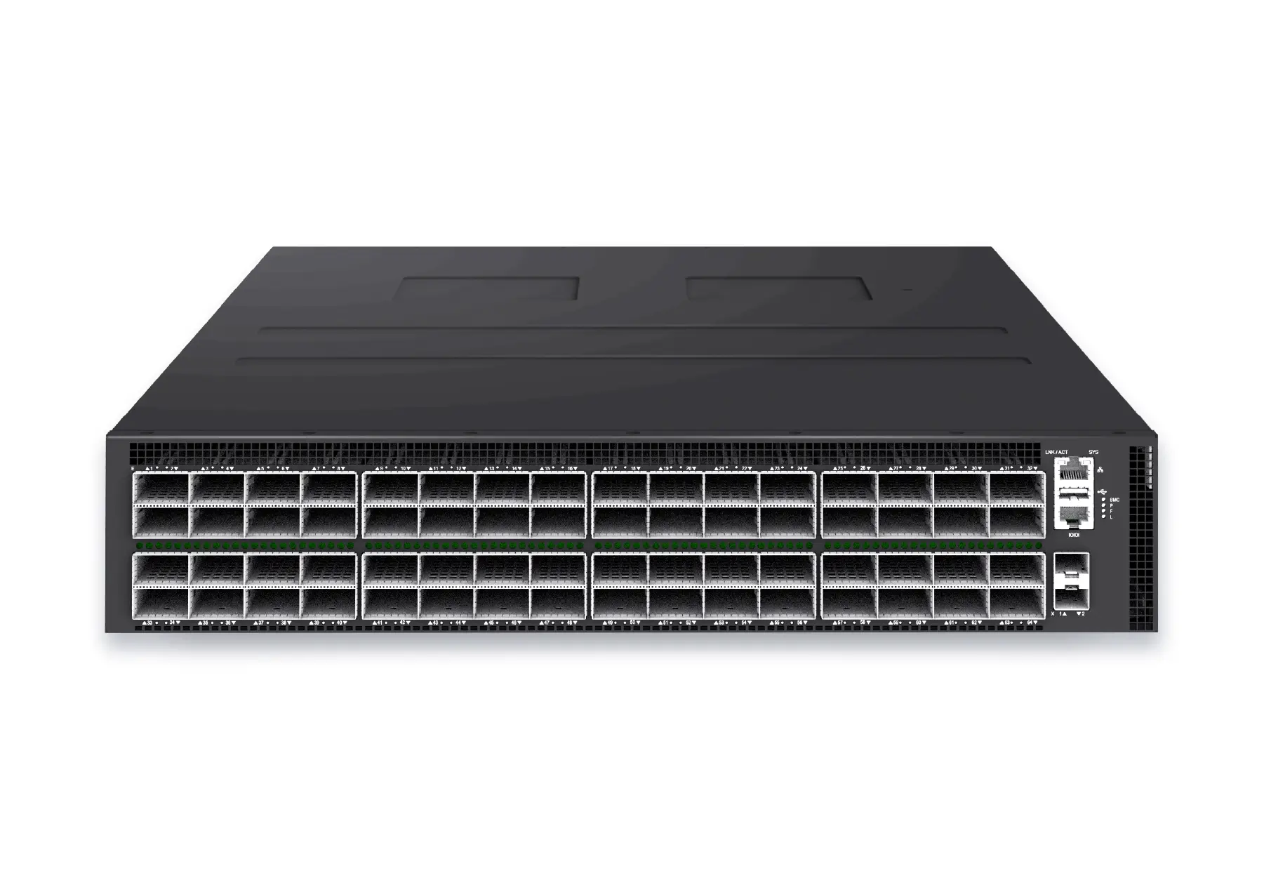 datacenter aiXS-DC-64X800-AI-G164-port 800G AI fabric switch for large-scale GPU clusters, HPC backbones, and ultra-high-throughput data center networks.View product
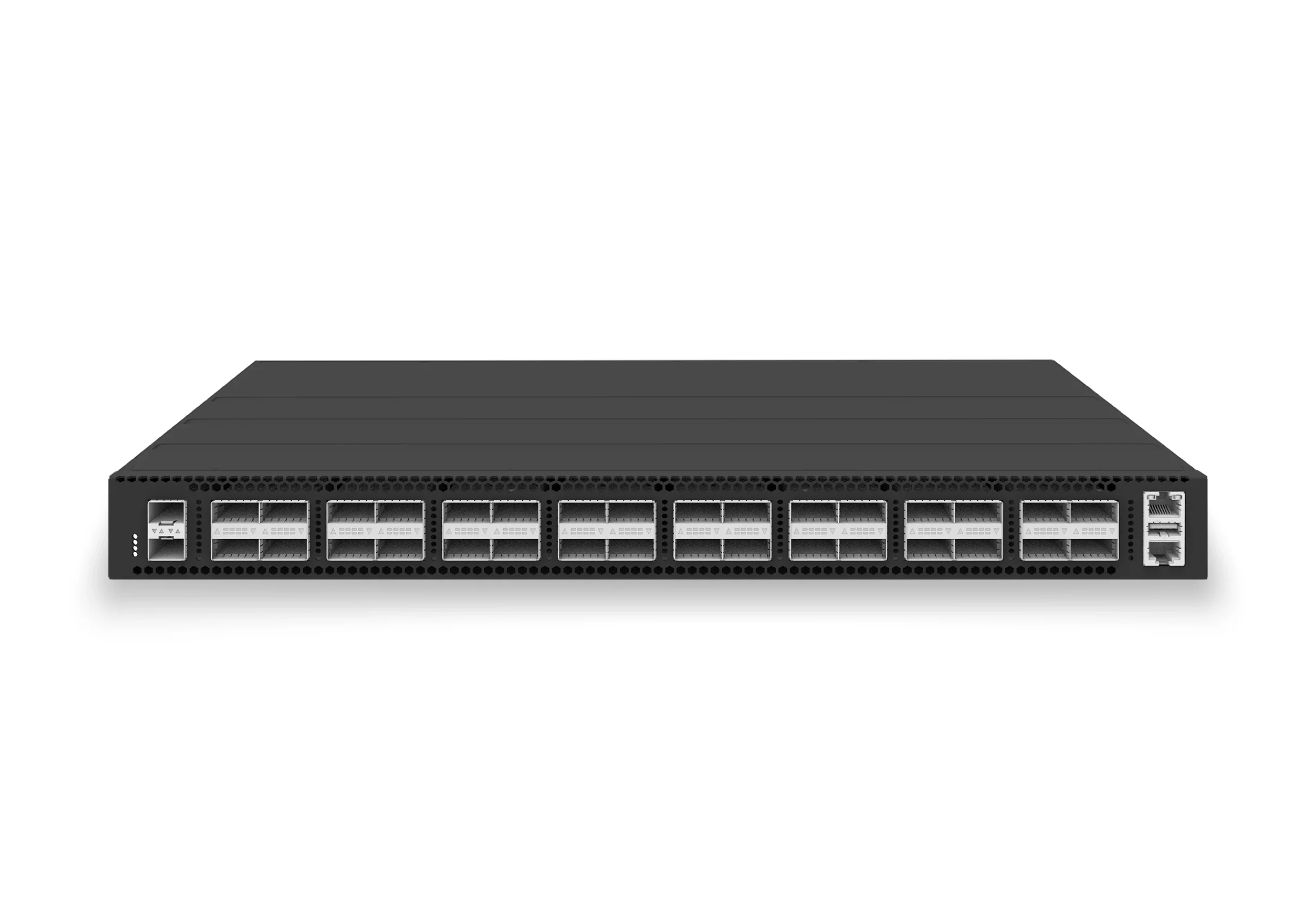 datacenter aiXS-DC-32X100-LS-G232-port 100G leaf/spine switch for VXLAN fabrics, RoCE-ready workloads, and tenant-scale routing.View product
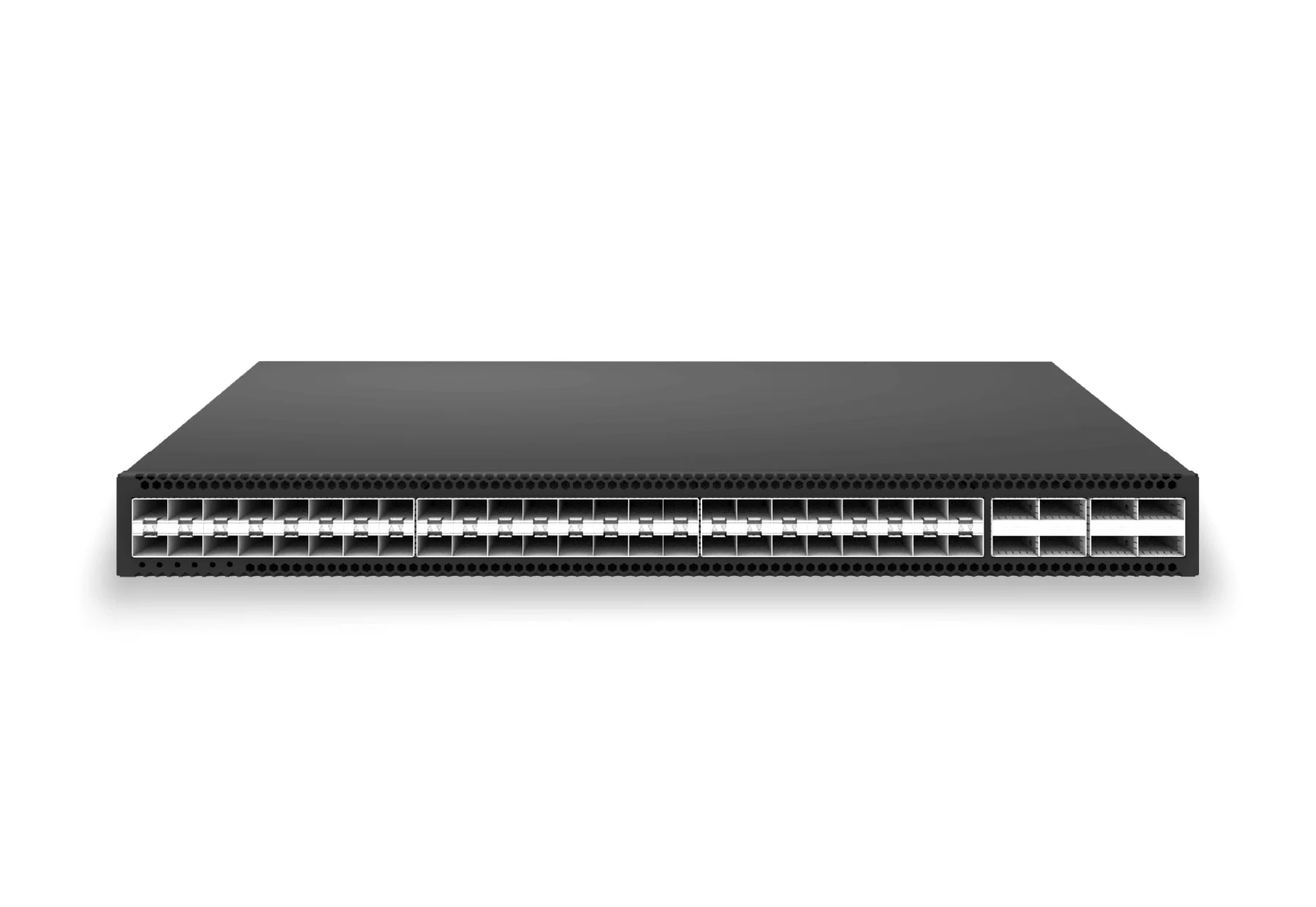 access aggregateXS-AA-48X25-8X100-AGG48x 25G SFP28 aggregation/core switch with 8x 100G QSFP28 for enterprise access and aggregation networks.View product
Continue reading
Related articles
 Technical ArticleWhy Enterprise SONiC Is Gaining Ground in Campus Access and Aggregation: An Australian PerspectiveEngineering guide for campus switching teams covering PoE, access design, MC-LAG/STP risk, telemetry, support, and pilot validation.Read article
 Technical ArticleCampus Access and Aggregation Refresh with Enterprise SONiCEngineering guide for campus switching teams covering PoE, access design, MC-LAG/STP risk, telemetry, support, and pilot validation.Read article
 Technical ArticlePoE Campus Planning Checklist for Enterprise SONiC Access SwitchesEngineering guidance on PoE Campus Planning Checklist for Enterprise SONiC Access Switches for Australian campus networks, covering RF planning, security controls.Read article