In brief
Engineering guidance on xSONiC 800G Data Center Switch Buyer Guide for Australian network teams, covering underlay design, EVPN-VXLAN operations, interoperability.
Key takeaways
- The move from 100G and 400G to 800G Ethernet in the data center is not a routine refresh.
- For Australian enterprises building private AI infrastructure -- whether for data sovereignty, cost predictability, or latency to local users -- the network fabric is no longer a commodity afterthought.
- 800G Ethernet addresses this demand by doubling the per-port bandwidth of 400G, reducing the number of links needed for high-radix spine-leaf topologies, and enabling fewer switches to serve more GPU endpoints.
Why 800G Matters for AI Infrastructure in 2025 and Beyond
The move from 100G and 400G to 800G Ethernet in the data center is not a routine refresh. It is being driven by a structural shift in workload architecture. AI training clusters, GPU inference farms, and large language model (LLM) serving pipelines demand massive east-west bandwidth with deterministic low latency. When GPU nodes communicate during distributed training, any network congestion or tail latency spike can stall an entire job, wasting expensive accelerator time.
For Australian enterprises building private AI infrastructure — whether for data sovereignty, cost predictability, or latency to local users — the network fabric is no longer a commodity afterthought. It is the performance backbone that determines whether a multi-million-dollar GPU investment delivers its promised throughput.
800G Ethernet addresses this demand by doubling the per-port bandwidth of 400G, reducing the number of links needed for high-radix spine-leaf topologies, and enabling fewer switches to serve more GPU endpoints. Industry data from the Ethernet Alliance and OCP indicates that 800G switch silicon is now available from multiple ASIC vendors, and early deployments are underway at hyperscale operators.
This guide walks Australian data center and enterprise network teams through the key decisions, trade-offs, and checklists involved in selecting and deploying 800G data center switches on SONiC-based open networking platforms.
Understanding SONiC: The Open NOS Foundation for 800G AI Fabrics
SONiC (Software for Open Networking in the Cloud) is a free and open-source network operating system based on Linux that runs on switches from multiple vendors and ASICs. It is a Linux Foundation project with backing from major cloud operators and network silicon vendors.
According to the SONiC Foundation, SONiC offers a full suite of network functionality including BGP and RDMA that has been production-hardened in the data centers of some of the largest cloud service providers. Its container-based architecture — where each network function runs in its own Docker container — provides better fault isolation, easier troubleshooting, simplified upgrades, and enhanced scalability compared to monolithic switch OS designs.
For 800G AI fabric deployments, SONiC offers several advantages relevant to Australian buyers:
- Multi-vendor hardware freedom: SONiC runs on switches from various hardware vendors, decoupling the NOS from the ASIC and chassis. This means you can evaluate 800G switch platforms on merit and price without being locked to a single vendor’s software ecosystem.
- RDMA and RoCE v2 support: SONiC supports RDMA over Converged Ethernet v2, which is essential for GPU backend fabrics where direct memory access between nodes eliminates CPU overhead during distributed training.
- Standard Linux tooling: Operations teams familiar with Linux can use standard interfaces and tools for monitoring, automation, and troubleshooting.
- Programmable and extensible: SONiC supports modern network programming paradigms, making it suitable for the telemetry-intensive, policy-driven operations that AI infrastructure demands.
The key architectural benefit for 800G deployments is the SAI (Switch Abstraction Interface) layer, which allows the same SONiC image to run on different 800G ASIC platforms. This abstraction accelerates hardware innovation by letting silicon vendors compete on switching capability while the software layer remains consistent.
800G Switch ASIC Landscape: What Buyers Need to Know
The 800G switch ASIC market is competitive, and the silicon choice determines much of what is possible in your fabric. The primary 800G-capable switch silicon families available as of 2025 include:
-
Broadcom Tomahawk 5: Broadcom’s Tomahawk 5 is a high-radix 800G switch ASIC used by multiple OEM/ODM switch vendors. It supports up to 51.2 Tb/s switching capacity in a single chip. Broadcom’s Tomahawk 5 is widely used in the open networking ecosystem and has SONiC support across multiple hardware platforms.
-
Marvell Teralynx family: Marvell offers 800G-capable switching silicon targeting data center and AI fabric use cases. SONiC support varies by platform.
-
Cisco Silicon One: Cisco’s Silicon One G200 supports 800G and is used in Cisco’s own Nexus platforms. SONiC support is limited to specific Cisco-approved configurations.
For Australian buyers evaluating SONiC-based 800G platforms, the Broadcom Tomahawk 5 and NVIDIA Spectrum-4 ecosystems have the broadest SONiC image availability and the most mature RDMA/RoCE feature sets. The choice between them often comes down to which ODM/OEM hardware partner is preferred, what optics ecosystem is planned, and which ASIC has better support for the specific telemetry and QoS features your AI fabric requires.
Decision criteria for ASIC selection:
| Criterion | Why It Matters for AI | What to Verify |
|---|---|---|
| RDMA/RoCE v2 support | GPU backend fabrics require zero-copy, low-latency memory access | Confirm RoCE v2, ECN, PFC, DCBX support in SONiC image |
| Congestion notification (CNP) | Fast CNP prevents packet drops during GPU collective operations | Verify Fast CNP implementation speed and configurability |
| Telemetry (INT/IPTPath) | In-band telemetry reveals microburst congestion invisible to SNMP | Confirm INT header insertion/extraction, IPTPath flow visibility |
| Buffer size and architecture | Deep buffers absorb microbursts common in AI training traffic | Check total buffer memory, per-port allocation, buffer pool architecture |
| Route scale | Large AI clusters may exceed 100K host routes | Verify FIB capacity for IPv4/IPv6 host and prefix routes |
| ACL and flow counter scale | Security segmentation and traffic engineering require large ACL tables | Confirm ACL entry count and flow counter depth |
AI Fabric Architecture: Spine-Leaf Design for 800G GPU Clusters
The standard architecture for 800G AI data center fabrics is the clos/spine-leaf topology. In this design, every leaf switch connects to every spine switch, creating a non-blocking, predictable-latency fabric. GPU servers connect to leaf switches, and east-west traffic between GPU nodes traverses exactly one hop through the spine layer.
For 800G AI clusters, the spine-leaf design parameters change compared to 100G or 400G fabrics:
Leaf tier:
- Each leaf switch provides 800G downlinks to GPU servers (typically 8x 100G or 2x 400G per server, depending on NIC configuration).
- Uplinks to the spine tier operate at 800G per port, with sufficient uplink bandwidth to prevent oversubscription.
- A non-blocking leaf requires equal downlink and uplink capacity.
Spine tier:
- Spine switches aggregate leaf uplinks and provide full-mesh connectivity.
- 800G spine switches with 64 or 128 ports of 800G enable large cluster scaling without adding a super-spine tier.
- For example, a 64-port 800G spine switch can serve 64 leaf switches. If each leaf serves 32 GPU servers (with 2x 400G NIC per server), a single-tier spine supports approximately 2,048 GPU endpoints in a non-blocking fabric.
Multi-tier scaling:
- Clusters larger than what a single spine tier can serve require a super-spine tier or multi-plane architecture.
- 800G with 51.2 Tb/s switch capacity significantly reduces the number of switches and racks needed compared to 400G, reducing power, cabling, and operational complexity.
AI-specific fabric considerations:
-
Traffic patterns: AI training generates many-to-many collective communication patterns (all-reduce, all-gather). These patterns produce microbursts that can overwhelm shallow buffers. Deep-buffer spine switches or well-tuned ECN/PFC are critical.
-
Deterministic latency: Training job completion time is sensitive to tail latency (99th percentile), not average latency. The fabric must deliver consistent sub-microsecond forwarding latency under load.
-
Fault tolerance: GPU jobs are synchronous. A single link failure or switch reboot can stall an entire training job. Redundant paths, fast failover, and graceful degradation are mandatory.
-
RDMA traffic isolation: RoCE v2 traffic for GPU communication must be isolated from management and storage traffic using VLANs, VXLANs, or VRF separation. DCBX (Data Center Bridging Capability Exchange) negotiation ensures PFC and ECN are consistently configured end-to-end.
Reference topology for 256-GPU cluster (32 servers x 8 GPUs each):
| Layer | Switch Role | Ports | Speed | Count |
|---|---|---|---|---|
| Leaf | Server-facing downlinks | 32 | 400G | 8 switches |
| Leaf | Spine uplinks | 8 | 800G | (per leaf) |
| Spine | Leaf-facing downlinks | 64 | 800G | 8 switches |
| Total | 16 switches + optics |
This topology uses 8 leaf switches (each with 32x 400G server-facing ports and 8x 800G uplinks) and 8 spine switches (each with 64x 800G ports, 8 used per spine for leaf connections). The result is a non-blocking 256-GPU fabric in 16 rack units of switching.
Engineering FAQ
What should be proven before adopting EVPN-VXLAN on SONiC? Prove underlay routing, BGP sessions, VTEP behaviour, MAC/IP learning, route scale, multi-homing design, failure convergence, and observability. The overlay should be accepted as a system, not a feature checkbox.
Why does the underlay design still matter in an overlay network? EVPN-VXLAN depends on a stable routed underlay. MTU, ECMP, addressing, route policy, link failure behaviour, and telemetry determine whether the overlay remains predictable under load and during faults.
What should be included in an EVPN-VXLAN operations runbook? Include naming, IP plan, BGP policy, VNI mapping, change process, rollback commands, failure checks, telemetry fields, backup and restore steps, and escalation ownership for the selected SONiC image.
Related xSONiC Resources
Sources Reviewed
- Ethernet Network Adapters - ConnectX NICs | NVIDIA
- NVIDIA BlueField Data Processing Unit
- NVIDIA Spectrum-X Ethernet Platform
- SONiC Project Documentation
- Broadcom Ethernet Switching
- Marvell Switching
- NVIDIA Ethernet Switching
- Open Compute Networking
- SONiC GitHub
- SONiC Foundation
Product fit
Products referenced for evaluation
These products are referenced for evaluation context in the article. Confirm workload, port, optics, software, interoperability, and support requirements against the exact deployment before procurement.
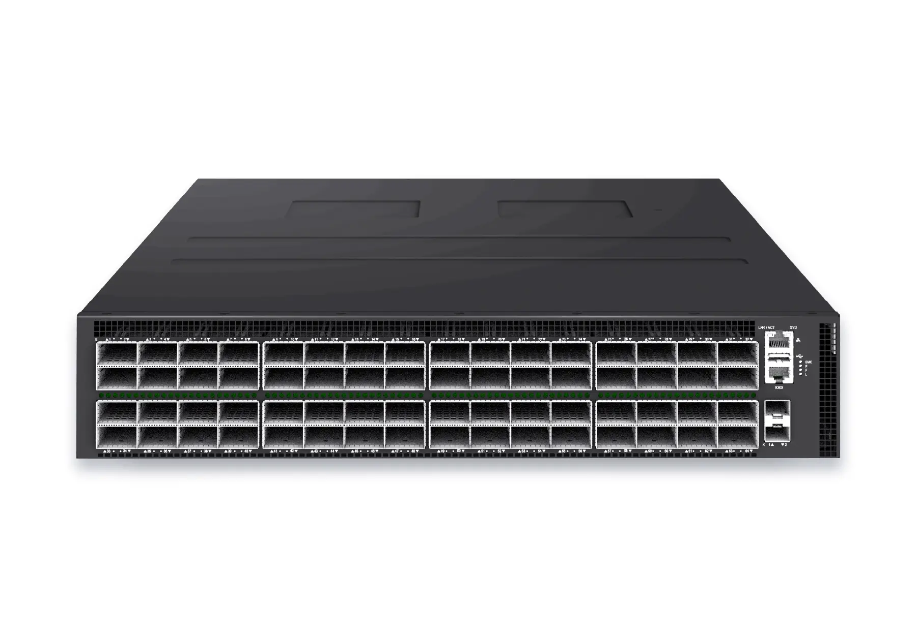 datacenter aiXS-DC-64X800-AI-G164-port 800G AI fabric switch for large-scale GPU clusters, HPC backbones, and ultra-high-throughput data center networks.View product
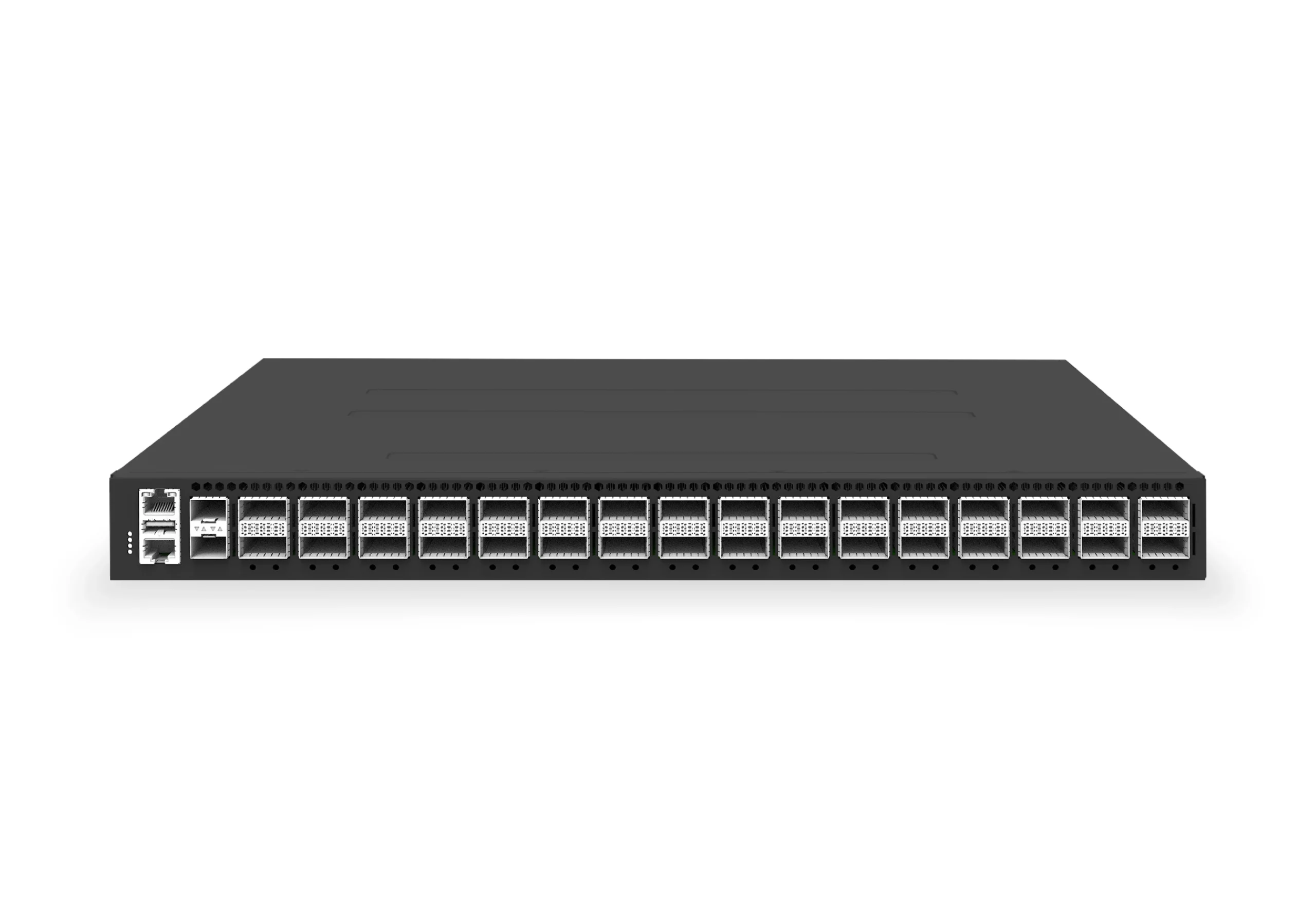 datacenter aiXS-DC-32X400-SP-G232-port 400G spine/core switch for high-capacity data center fabrics and AI-ready backbones.View product
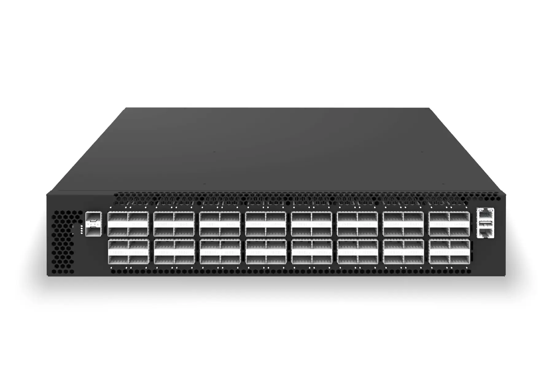 datacenter aiXS-DC-64X200-LS-G164-port 200G leaf/spine switch for high-bandwidth storage, compute, and scale-out data center fabrics.View product
Continue reading
Related articles
 Technical ArticleDesigning GPU Backend Fabrics with RoCE v2: How SONiC 400G/800G Switches Transform AI Data CentersEngineering guide for AI fabric buyers covering RoCE, SONiC, telemetry, optics, support ownership, and deployment validation.Read article
 Technical ArticleWhy Open SONiC Ethernet Is Becoming the Default AI Fabric for GPU Backend ClustersEngineering guidance on Open SONiC Ethernet Is Becoming the Default AI Fabric for GPU Backend Clusters for Australian network teams, covering underlay design.Read article
 Technical ArticleGPU Cluster Fabric Design: Why AI Workloads Need Purpose-Built EthernetArchitecture guide to GPU cluster fabrics covering RoCE v2, PFC, ECN, DCBX, SONiC, 400G/800G, telemetry, InfiniBand trade-offs, and acceptance evidence.Read article