In brief
Capacity planning guidance for U.2, E1.S, M.2, and AIC NVMe SSD procurement across enterprise storage, AI, thermal, and serviceability needs.
Key takeaways
- Procurement leads in Australian enterprise and data center programs face a structural decision before a single drive is ordered: which NVMe SSD form factor fits each workload tier, server platform, and rack design.
- Australia adds its own constraints. Sovereign data requirements, long supply-chain lead times for specialized components, limited local stock of newer EDSFF form factors, and the rapid expansion of liquid-cooled AI clusters at facilities like Macquarie Data Centres all shape which form factors are practical to standardize on today versus which deserve a pilot program.
- Before diving into capacity math, it helps to align on what each form factor physically looks like and where it typically sits in a server or storage platform.
Why Form Factor Choice Drives Capacity Planning Outcomes
Procurement leads in Australian enterprise and data center programs face a structural decision before a single drive is ordered: which NVMe SSD form factor fits each workload tier, server platform, and rack design. The choice between U.2, E1.S, M.2, and AIC is not cosmetic. It directly affects how many terabytes per rack unit you can deploy, whether drives are hot-swappable in production, how thermal loads distribute across a chassis, and how your storage tier maps to AI training, inference, database, VDI, and archival workloads.
Australia adds its own constraints. Sovereign data requirements, long supply-chain lead times for specialized components, limited local stock of newer EDSFF form factors, and the rapid expansion of liquid-cooled AI clusters at facilities like Macquarie Data Centres all shape which form factors are practical to standardize on today versus which deserve a pilot program. This guide gives procurement teams a structured model for comparing U.2, E1.S, M.2, and AIC across the dimensions that matter most when you are committing storage budget at scale.
The Four Enterprise NVMe Form Factors at a Glance
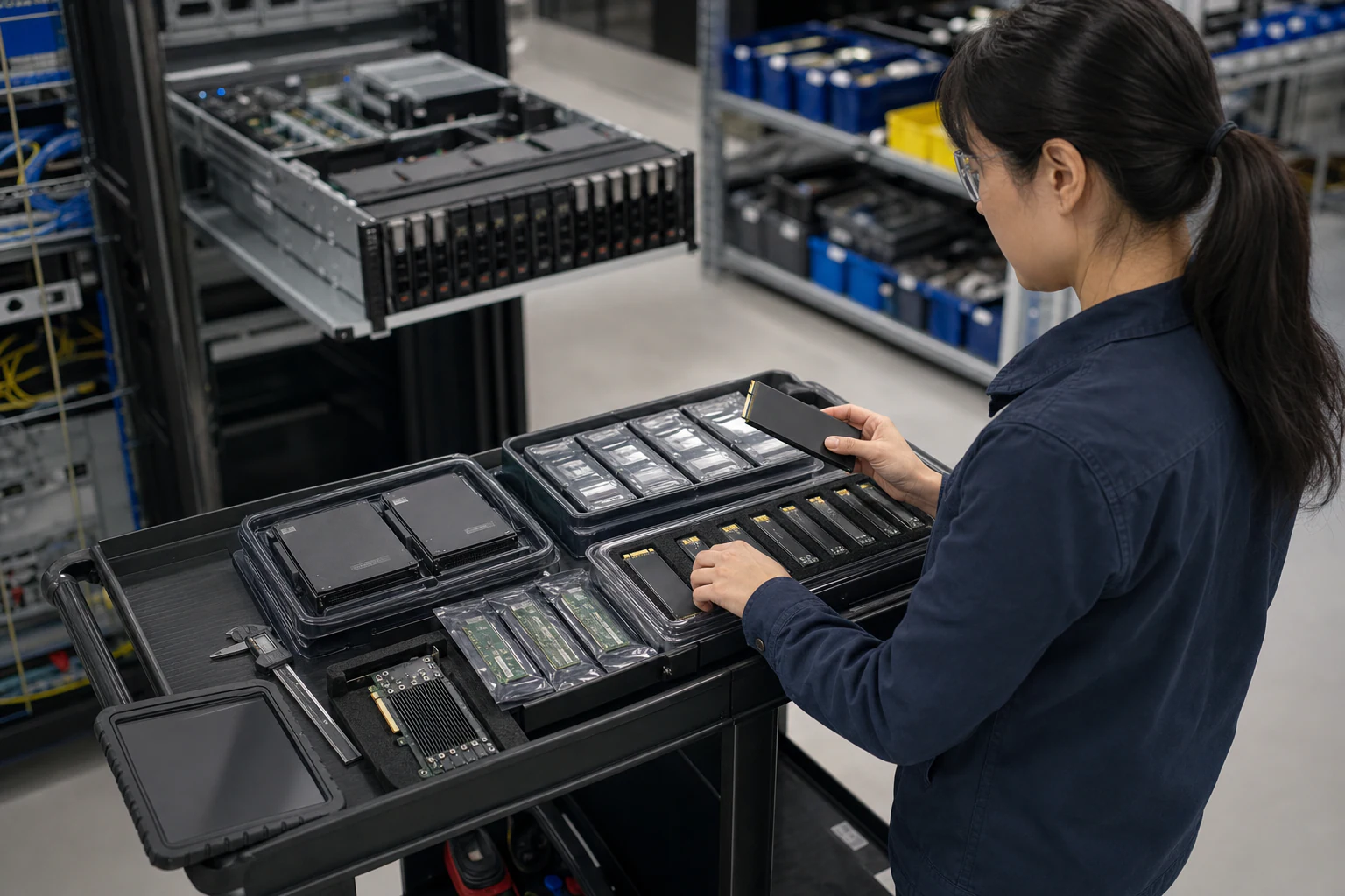
Before diving into capacity math, it helps to align on what each form factor physically looks like and where it typically sits in a server or storage platform.
U.2 (2.5-inch, 15mm) is the legacy enterprise standard. It uses a 2.5-inch bay with a U.2 connector (SFF-8639) and supports hot-swap serviceability. Most 1U and 2U rack servers ship with U.2 bays as a default. Capacities commonly range from 800 GB to 15.36 TB per drive in enterprise TLC configurations, with higher-density QLC options emerging. U.2 remains the workhorse for general-purpose enterprise storage, VMware datastores, SQL databases, and object storage nodes.
E1.S (EDSFF Short) is the newer OCP-aligned form factor designed for density-optimized 1U and 2U platforms. At roughly 32mm wide and available in multiple heights (5.9mm, 8.01mm, 15mm, 25mm with heatsink), E1.S allows significantly more drives per rack unit than U.2. A 1U server can accommodate 16 to 32 E1.S slots depending on the chassis design, compared to 4 to 10 U.2 bays. E1.S also supports hot-swap in sled-based designs and is gaining traction in cloud-scale and AI data center builds.
M.2 (2280, 22110) is a compact internal form factor typically used for boot drives, OS partitions, and read-intensive caching layers. M.2 drives are not hot-swappable in most server designs and are usually mounted internally on the motherboard or a riser card. Enterprise M.2 drives range from 240 GB to 3.84 TB and are best suited for roles where the drive does not need field replacement during normal operations.
AIC (Add-in Card, half-height half-length or full-height) slots into a standard PCIe x4, x8, or x16 slot. AIC NVMe drives deliver the highest per-drive performance because they can use wider PCIe lanes and larger PCB areas for controller and NAND placement. Capacities reach up to 30 TB or more in enterprise configurations. AIC is common in HPC, AI training data staging, and high-throughput database workloads where maximum bandwidth per drive matters more than bay density.
Capacity Density: How Many Terabytes Per Rack Unit
The most important procurement metric for large-scale programs is raw capacity per rack unit (TB/RU). This determines how much floor space, power, and cooling your storage consumes relative to the usable capacity delivered.
U.2 in a typical 2U server with 24 bays at 15.36 TB per drive yields approximately 368 TB in 2 RU, or about 184 TB/RU. This is a well-understood baseline that most Australian procurement teams already have in their fleet.
E1.S in a density-optimized 1U chassis with 32 slots at 7.68 TB per drive yields approximately 245 TB in 1 RU. At 15.36 TB per E1.S drive (as higher-density EDSFF options become available), that figure climbs to approximately 491 TB/RU. Even at current mainstream densities, E1.S delivers 25 to 35 percent more TB/RU than U.2.
M.2 is not a density play for bulk storage. A server with 2 M.2 boot drives at 1.92 TB each contributes only 3.84 TB, typically mirrored for redundancy. M.2 capacity is negligible in rack-level planning but critical for OS reliability.
AIC in a 2U server with 4 to 8 PCIe slots depends on the platform. At 15.36 TB per AIC drive and 8 slots, a 2U server delivers approximately 122 TB in 2 RU, or about 61 TB/RU. AIC trades density for per-drive bandwidth, so it is not the right choice when maximizing TB/RU is the primary goal.
Procurement takeaway: If your program prioritizes capacity density, E1.S is the clear leader, followed by U.2. AIC and M.2 serve different roles in the storage hierarchy.
Workload Mapping: Which Form Factor Fits Which Tier
A disciplined capacity planning model assigns form factors to workload tiers rather than defaulting everything to one form factor. Here is a practical tiering framework for Australian enterprise and data center programs.
Tier 1 - Boot and OS: Use enterprise M.2 drives in RAID-1 mirror pairs. These are internal, low-power, and reliable enough for operating system partitions on hypervisor hosts, bare-metal Kubernetes nodes, and GPU inference servers. M.2 keeps the U.2 and E1.S bays free for data volumes.
Tier 2 - General Enterprise Storage (VMs, databases, file services): U.2 remains the standard choice. Most server OEMs ship U.2 bays as the default, enterprise U.2 SSDs are widely available in Australia through multiple distribution channels, and hot-swap serviceability keeps MTTR low. For VMware vSAN, Microsoft Storage Spaces Direct, or Ceph clusters, U.2 provides the best balance of capacity, endurance, and operational simplicity.
Tier 3 - Cloud-Scale and AI Data Staging: E1.S is the target form factor for new greenfield builds. If your program is deploying 1U density-optimized servers for AI inference, object storage, or distributed caching, E1.S maximizes drive count per chassis. This matters for AI pipelines that stripe small files across many drives for parallel read throughput during model training data loading.
Tier 4 - High-Bandwidth Database and HPC Scratch: AIC drives are the right fit for Oracle RAC, SAP HANA, or HPC scratch volumes where a single application needs maximum sequential throughput or sustained random IOPS per drive. AIC also works well as a local NVMe tier on GPU inference servers where data must be staged as close to the GPU as possible.
Procurement takeaway: Do not standardize on a single form factor. Build a tiered model that matches M.2 for boot, U.2 for general-purpose, E1.S for density, and AIC for peak-performance workloads.
Serviceability and Operational Risk in Australian Data Centers
Australian enterprise programs often operate across a mix of on-premises data centers, colocation facilities (NextDC, Equinix, Macquarie), and edge sites in regional locations. Serviceability varies significantly by form factor and matters more when your nearest qualified field engineer is a flight away.
U.2 hot-swap is the gold standard for operational serviceability. A failed U.2 drive can be replaced by on-site data center technicians without opening the server chassis. This is well-understood by all major Australian server OEM support teams and colocation remote-hands services.
E1.S hot-swap is supported in sled-based chassis designs, but not all E1.S platforms support hot-swap equally. Procurement teams should verify that the specific chassis and backplane combination supports hot-swap before committing to E1.S as the primary form factor. In Australian deployments where colocation remote-hands may be unfamiliar with E1.S, training and documentation should be part of the deployment plan.
M.2 is not field-serviceable in most server designs. A failed M.2 boot drive typically requires partial chassis disassembly. For this reason, M.2 drives should always be deployed in mirror pairs, and the mean time between failure (MTBF) rating should be verified against the expected host lifecycle.
AIC replacement requires opening the server chassis and accessing the PCIe slot. This is more disruptive than U.2 or E1.S hot-swap but is acceptable for AIC’s typical role in performance-critical workloads where the drive is part of a larger server maintenance cycle anyway.
Procurement takeaway: For Australian programs with distributed edge sites or reliance on colocation remote-hands, U.2 and E1.S hot-swap are the safest operational choices. M.2 boot mirrors and AIC deployments should be paired with clear service documentation.
Power, Thermal, and Cooling Considerations
Power draw per drive and the resulting thermal envelope are capacity planning inputs that procurement leads sometimes overlook until the rack power budget is already committed.
U.2 enterprise SSDs typically draw 5 to 12 watts active depending on capacity and workload. In a 2U server with 24 bays, this adds 120 to 288 watts of drive-level power that must be accounted for in the server and rack power budget.
E1.S drives draw similar per-drive power to U.2 (5 to 12 watts), but the higher drive density per rack unit means total storage power per RU is 25 to 35 percent higher than U.2. In a 1U chassis with 32 E1.S slots, peak drive power alone could reach 256 to 384 watts. This must be factored into the rack-level power and cooling design, especially in Australian colocation facilities where per-rack power allocations may be contractually capped.
M.2 enterprise drives draw 3 to 6 watts active. Two mirrored M.2 boot drives add negligible load to the server power budget.
AIC PCIe NVMe drives draw 10 to 25 watts active depending on the drive capacity and controller design. With 4 to 8 AIC drives per server, total AIC power can range from 40 to 200 watts, and the PCIe slot placement means heat is concentrated near the CPU and memory zone.
For Australian AI data center builds that are adopting liquid cooling (as discussed in the OCP Podcast episode featuring Macquarie Data Centres CEO David Hirst), E1.S and AIC form factors can benefit from direct liquid cooling integration, but this requires coordination with the chassis and CDU design. Procurement teams should engage with their server OEM and cooling infrastructure vendor early in the planning cycle.
Procurement takeaway: Always model per-rack storage power alongside compute power. E1.S density comes with a thermal cost that must be planned for in rack power budgets and cooling capacity.
Australian Supply Chain and Availability Realities
Form factor selection is not just a technical decision. It is a supply chain decision, and the Australian market has specific constraints that procurement leads must account for.
E1.S is newer and less widely stocked in Australia. While hyperscalers and large cloud providers have moved aggressively to E1.S, the Australian enterprise market is still transitioning. Procurement teams planning E1.S deployments should expect longer lead times, especially for high-density configurations (15.36 TB per E1.S). Early engagement with distribution partners and the option to qualify a secondary U.2 fallback configuration are prudent risk mitigations.
M.2 enterprise SSDs are widely available but in a narrower range of capacities and endurance ratings compared to U.2. Procurement teams should specify enterprise-grade M.2 (not client/consumer M.2) to ensure power-loss protection, end-to-end data path protection, and appropriate DWPD ratings.
AIC enterprise SSDs are available but in lower volume than U.2 in the Australian market. AIC drives tend to be ordered for specific HPC or database projects rather than general fleet procurement.
Procurement Acceptance Matrix
The procurement record should prove that the chosen form factor supports the workload and the operating model. Treat capacity, thermals, serviceability, and lead time as one engineering decision rather than four independent spreadsheet columns.
| Procurement area | Acceptance evidence | Rework trigger |
|---|---|---|
| Capacity density | TB/RU calculated for U.2, E1.S, M.2, and AIC using the proposed chassis and usable capacity target | Raw drive capacity is compared without RAID, erasure coding, spare, or overprovisioning assumptions |
| Thermal and power | Drive watts, chassis airflow, inlet temperature, and throttling counters tested for at least 24 hours | E1.S or AIC drive throttles during sustained write or mixed 70/30 workload |
| Serviceability | U.2 and E1.S hot-swap process validated; M.2 and AIC replacement steps documented for remote hands | Replacement requires unplanned GPU, NIC, or riser removal in production |
| PCIe topology | Gen4/Gen5 negotiation, x4/x8/x16 lane mapping, and BIOS bifurcation settings recorded | Drive shares lanes with a NIC or accelerator in a way that breaks the performance model |
| Supply risk | Primary and secondary qualified SKUs documented with 8-week and 16-week lead-time scenarios | E1.S or AIC selection has no approved fallback if Australian stock is delayed |
Engineering FAQ
How should NVMe form factor selection be made? Start with workload profile, usable capacity, serviceability, thermal envelope, write endurance, PCIe generation, slot layout, and replacement process. U.2, E1.S, M.2, and AIC devices solve different mechanical and operational problems.
What matters more than peak sequential speed? Sustained performance, thermal throttling behaviour, write endurance, latency under load, firmware stability, power-loss protection, and fleet manageability usually matter more than a single benchmark number.
How should storage be validated for AI or cloud workloads? Test the selected form factor in the real chassis with expected airflow, queue depth, write mix, temperature range, and monitoring stack. Validation should include steady-state and recovery behaviour, not only fresh-drive performance.
Related xSONiC Resources
Sources Reviewed
- NVM Express Specifications for NVMe SSDs
- PCI-SIG PCI Express Specifications
- SNIA Storage Form Factors and SFF Specifications
- SNIA EDSFF Enterprise and Data Center SSD Form Factor Work
- Open Compute Project NVMe Cloud SSD Specification
- xSONiC U.2 NVMe SSD Product
- xSONiC E1.S NVMe SSD Product
- xSONiC AIC NVMe SSD Product
Product fit
Products referenced for evaluation
These products are referenced for evaluation context in the article. Confirm workload, port, optics, software, interoperability, and support requirements against the exact deployment before procurement.
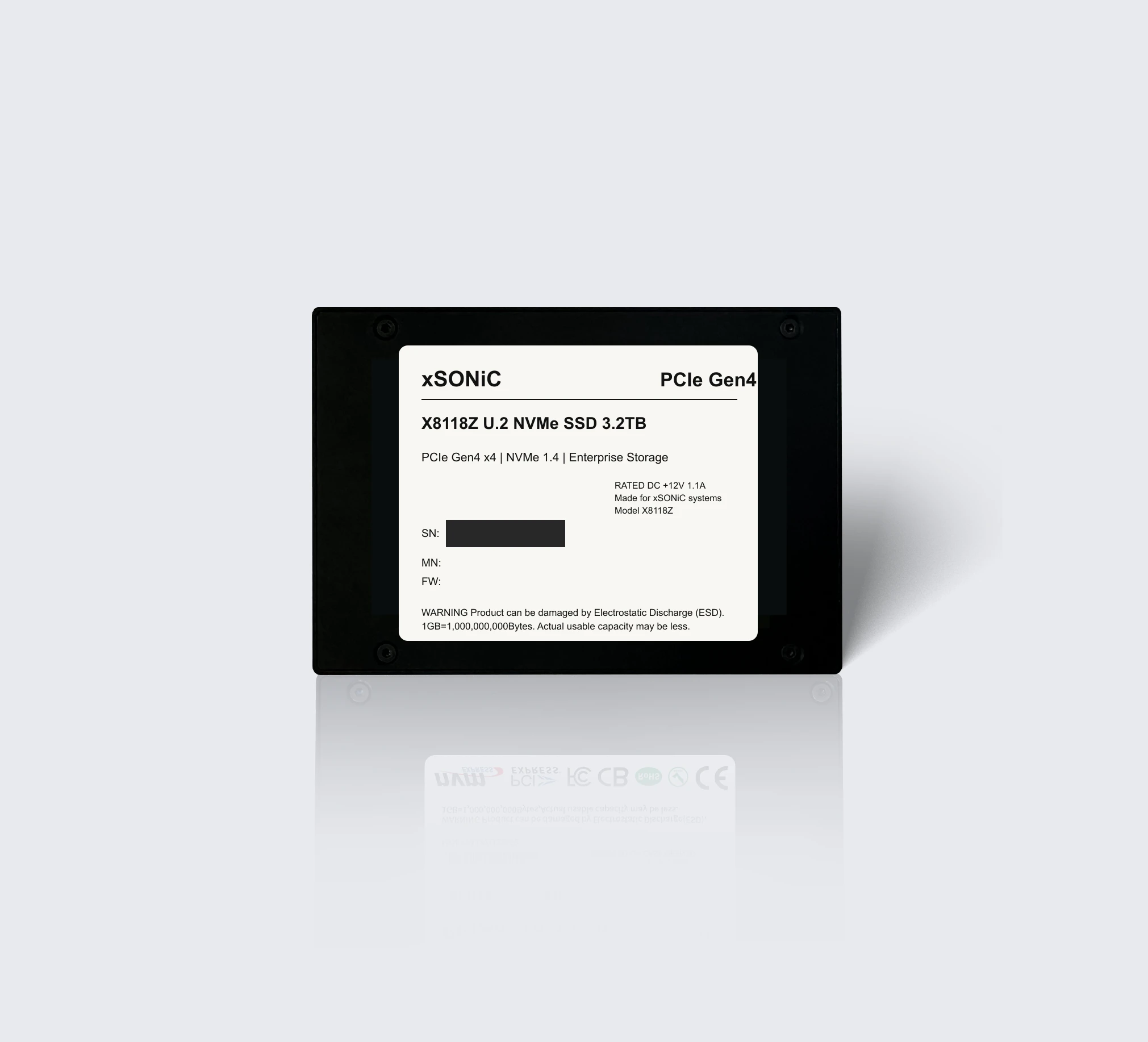 nvme ssdXS-SSD-8118Z-U2Enterprise U.2 NVMe SSD with PCIe Gen4 x4, NVMe 1.4, up to 7.1 GB/s sequential read, and 1,000K IOPS for data center storage workloads.View product
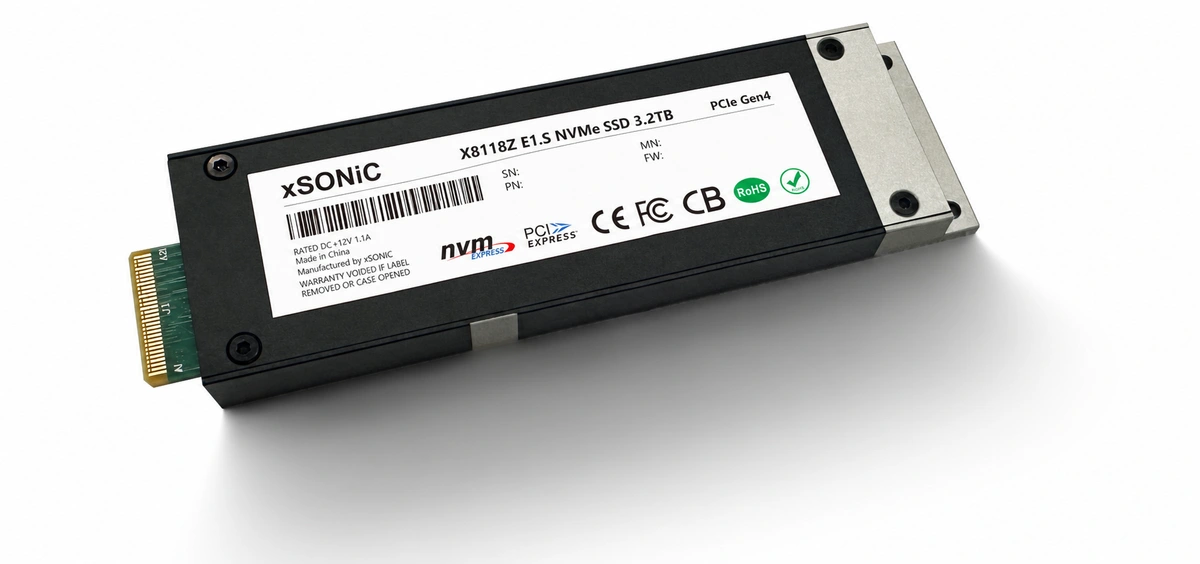 nvme ssdXS-SSD-8118Z-E1SEnterprise E1.S NVMe SSD with PCIe Gen4 x4, up to 7.1 GB/s sequential read, 1,000K IOPS, and compact data center storage density.View product
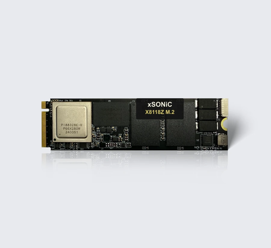 nvme ssdXS-SSD-8118Z-M2Enterprise M.2-2280 NVMe SSD with PCIe Gen4 x4, up to 7.1 GB/s sequential read, 1,000K IOPS, and compact storage deployment flexibility.View product
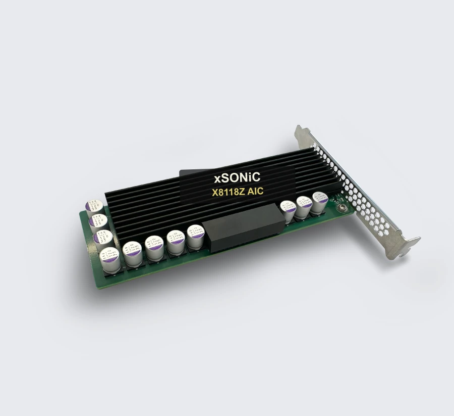 nvme ssdXS-SSD-8118Z-AICEnterprise AIC NVMe SSD with PCIe Gen4 x4, up to 7.0 GB/s sequential read, 1,000K IOPS, and add-in-card deployment flexibility.View product
Continue reading
Related articles
 Technical ArticleNVMe SSD Form Factor Comparison: U.2 vs E1.S vs M.2 vs AIC for Enterprise and AI WorkloadsAn engineering comparison of U.2, E1.S, M.2, and AIC NVMe SSD form factors for enterprise storage, AI workloads, thermals, and serviceability.Read article
 Technical ArticleEnterprise NVMe SSD Form Factors for AI Storage and Cloud Workloads: A Buyer's GuideCompare U.2, M.2, E1.S, and AIC NVMe SSD form factors for enterprise AI storage, cloud databases, HPC, thermals, and serviceability.Read article
 Technical ArticleWhy AI Infrastructure Demands Are Reshaping Enterprise NVMe SSD Form Factor Choices in AustraliaEngineering guide to NVMe SSD form factor choices for Australian AI infrastructure, covering U.2, M.2, E1.S, AIC, thermals, endurance, and validation.Read article