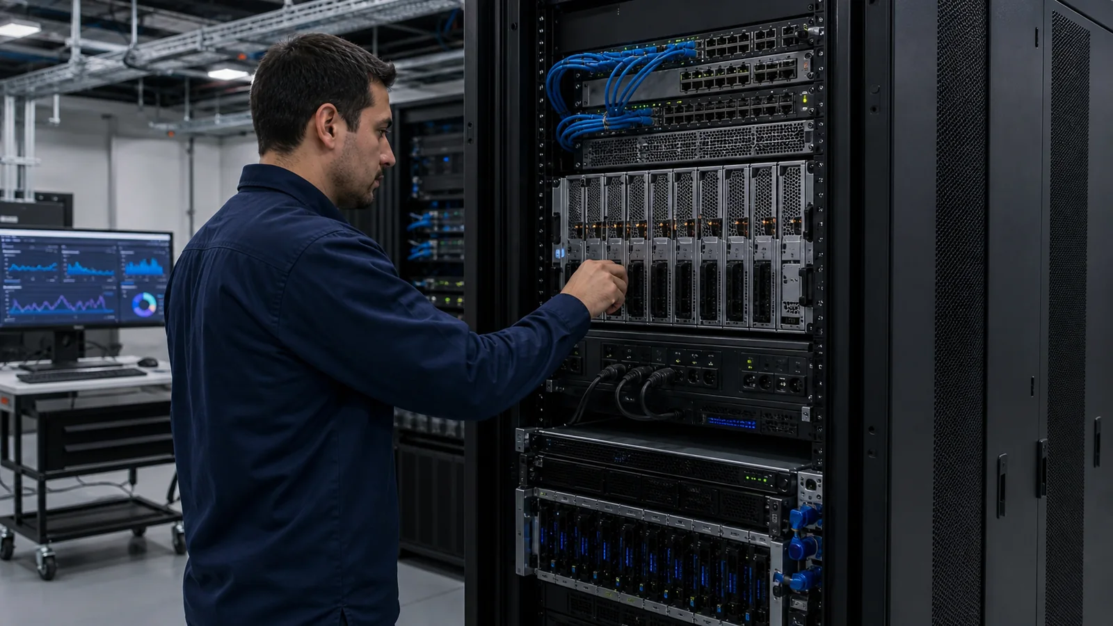
In brief
An on-premises LLM deployment is ready only when seven domains have written evidence: power; cooling; rack and delivery logistics; production, management, and storage networking; storage tiers; observability; and measured validation with an operational handover. Start with the exact server configuration and target workload, then close every unanswered row in the checklist before the delivery date.
Key takeaways
- Use the exact configured system input and thermal specifications; a model-family or GPU-only figure is not a site design.
- Power and cooling are coupled: almost all electrical input becomes heat that the room or liquid loop must reject.
- Treat model files, vector data, document corpora, and logs as distinct storage workloads with different performance and governance needs.
- Separate production, storage, and management traffic according to the failure and security boundaries the service requires.
- Acceptance means reproducible workload results at a declared p95 target, plus dashboards, runbooks, configuration records, and named support ownership.
An inference node can pass a factory test and still be impossible to deploy in the intended room. The gap is usually not accelerator capability. It is a missing feed, an unsupported cooling method, an unsuitable rack, an under-sized data path, or an acceptance plan that was never written.
Use the following seven domains as evidence gates. Each owner should attach a document, drawing, measurement, or approved decision to every question. A verbal assurance is useful during discovery, but it is not a deployment artefact.
1. Power: can the site feed the configured system?
Begin with the maximum input requirement for the complete server configuration. Do not substitute accelerator thermal design power, an average telemetry reading, or a value copied from another chassis. The facilities review needs the system’s documented voltage range, input current, connectors, feed arrangement, power-supply redundancy, and any derating or headroom rules that apply locally.
Walk that requirement upstream:
- Confirm that rack PDUs and receptacles match the connector and current requirements.
- Identify the circuits and breaker capacity, including the sustained-load policy used by the site.
- Draw the A and B paths. Dual power supplies do not provide end-to-end redundancy if both paths terminate on the same upstream failure point.
- Decide what the UPS and generator-backed scope includes, and document the expected service behaviour during a loss of utility power.
- Reserve capacity for switches, storage, management equipment, and cooling auxiliaries rather than assigning the entire rack allowance to the server.
The output of this gate is a signed power schedule tied to the exact bill of materials, not a generic statement that the room has “enough power”.
2. Cooling: where will the heat go?
Nearly all electrical input becomes heat that must leave the equipment and facility. That makes cooling the other side of the power decision.
Confirm whether the selected configuration is supported with air cooling, direct liquid cooling, or another documented method. For an air-cooled system, verify front-to-back airflow, inlet-temperature limits, hot-aisle and cold-aisle separation, return-air paths, and the room’s remaining sensible-cooling capacity. Look for recirculation around empty rack spaces and cable openings; small bypass paths can make a room-level capacity figure misleading.
For a liquid-cooled option, document coolant-distribution-unit capacity, supply and return conditions, water-quality requirements, manifolds, hoses, leak detection, isolation, service procedures, and how heat is rejected from the facility loop. “Liquid-ready” is not the same as a commissioned loop.
Monitor conditions at equipment inlets rather than relying only on a room thermostat. The evidence for this gate is the configuration’s supported thermal method, a facility heat-load calculation, and monitored environmental limits agreed by the server and facilities teams.
3. Rack and physical delivery: will the system fit safely?
Dense GPU systems are deep, heavy, and difficult to manoeuvre. Check the released dimensions, operating mass, rail kit, rack-post spacing, cable bend radii, service clearances, and rack loading before shipment.
Then inspect the whole delivery route: loading dock, thresholds, corridor turns, lift dimensions and capacity, floor loading, ramps, and the lifting or installation equipment required at the rack. Plan the rack elevation so heavy equipment sits at an appropriate height and does not block the intended airflow.
Reserve adjacent rack units and cable paths for switching, storage, PDUs, management equipment, and horizontal or vertical cable management. The output is a marked rack elevation plus a measured delivery-path record. Those two documents prevent the avoidable failure of equipment arriving at a room it cannot safely enter or occupy.
4. Network: treat the fabric as part of the service
Separate the network requirement into flows before choosing speeds:
| Traffic flow | Typical purpose | Questions that must be answered |
|---|---|---|
| Storage and east-west | Model loading, vector queries, document retrieval, node-to-node traffic | What are the measured throughput and latency requirements? What oversubscription and failure behaviour are acceptable? |
| Service ingress and north-south | User and application access to inference APIs | Where are authentication, rate limits, TLS termination, load balancing, and policy enforced? |
| Management | BMC, operating-system administration, monitoring, firmware, and recovery | Is it isolated from production traffic, reachable during an incident, and governed by privileged-access controls? |
Match switches, optics, cabling, breakout modes, host adapters, MTU policy, and resilience to those flows. A 400G label may be appropriate for a dense design, but a speed label alone does not establish usable performance or a recoverable topology. The private-AI network and storage planning guide provides a deeper buyer framework, while the GPU networking deployment playbook covers fabric implementation.
The gate closes when the logical diagram, physical port map, optic and cable schedule, addressing and management plan, and failure tests are all assigned.
5. Storage: size several workloads, not one capacity number
Private inference usually contains at least four storage behaviours:
| Data class | Dominant behaviour | Evidence to collect |
|---|---|---|
| Model repository | Large sequential reads during load, restart, or model replacement | Model inventory, version allowance, measured load time, integrity and rollback process |
| Vector index | Latency-sensitive random access with growth tied to the corpus | Query latency and IOPS under representative retrieval load, rebuild procedure, capacity forecast |
| Source documents and evaluation data | Governed capacity, access control, lifecycle, and backup | Ownership, permissions, retention, backup, recovery point and recovery time targets |
| Service logs and traces | Sustained writes, bursts during faults, potentially sensitive request metadata | Ingestion rate, retention, access control, redaction, export, and deletion policy |
Size each class on the axis that governs it. Model storage needs enough sequential throughput to meet restart objectives. Vector data needs latency and IOPS headroom. Documents need governance and recovery. Logs need an explicit privacy and retention decision.
Measure the full path, not only the SSD. File systems, network mounts, storage controllers, encryption, and contention can all move the result. A capacity figure without a load-time and recovery objective does not close this gate.
6. Observability: instrument before production traffic
Observability should identify whether a slow request waited on queueing, prefill, decode, storage, networking, or a failing component. Establish a minimum set before launch:
- request rate, queue depth, time to first token, output rate, and p50/p95 latency by model and version;
- accelerator memory occupancy, utilisation, temperature, power, throttling, and error signals exposed by the platform;
- host, network-interface, switch-port, storage, and file-system health;
- model-load and restart events, application errors, and saturation signals;
- logs and traces with deliberate redaction, access, and retention rules.
Build dashboards around service objectives and assign each alert to an owner. Test alert paths by inducing safe, controlled conditions before users depend on them. The GPU network observability guide is a useful companion for the fabric layer.
The gate is not closed by installing an exporter. It closes when an operator can use the dashboards and runbook to explain a degraded request and reach the right escalation path.
7. Validation and handover: define “done” as evidence
Write the acceptance profile before the final configuration is approved. It should name the target model and version, precision, serving-stack version, input and output length distributions, concurrency pattern, request mix, latency objective, and any RAG or multimodal work included in the service.
Replay that profile on the deployed system. Record sustained throughput, time to first token, p50 and p95 latency, queue behaviour, errors, storage and network signals, and the test duration. Probe beyond the planned operating point to show how the service degrades, but do not label a stress-test peak as production capacity.
Handover should include:
- the approved configuration and network records;
- model deployment, update, rollback, backup, and recovery procedures;
- dashboards, alert thresholds, log-retention settings, and access controls;
- routine health checks and maintenance responsibilities;
- support contacts, severity definitions, and escalation times;
- the raw test conditions and results needed to reproduce acceptance after a change.
A power-on test proves installation. Reproducible results and an operable runbook prove deployment.
One-page deployment readiness matrix
Use this table as the project risk register. Record an owner, evidence link, and due date beside every unresolved question in the working copy.
| Domain | Questions to answer in writing | Minimum acceptance evidence |
|---|---|---|
| Power | Do feeds, circuits, breakers, PDUs, connectors, redundancy, and continuity scope match the exact configured system? | Configuration-specific power schedule and A/B path drawing |
| Cooling | Is the supported cooling method commissioned, and can the facility reject the full design heat load within inlet limits? | Thermal calculation, method statement, and inlet monitoring |
| Rack and physical | Do depth, rails, mass, floor loading, elevation, service clearance, and delivery path work? | Approved rack elevation and measured logistics record |
| Network | Are storage, ingress, and management flows sized, secured, resilient, and documented? | Logical and physical diagrams, port map, bill of materials, and failure tests |
| Storage | Are model, vector, document, and log tiers sized and governed on their own requirements? | Capacity plan, path measurements, load-time result, and recovery plan |
| Observability | Can operators see service latency, queueing, accelerators, hosts, fabric, storage, errors, and retention state? | Live dashboards, tested alerts, ownership, and retention settings |
| Validation and handover | Was the representative workload measured at the declared latency target, and can the receiving team operate it? | Signed test report, configuration record, runbook, and escalation path |
Keep adjacent workstreams visible
This checklist covers infrastructure readiness. It does not replace model and precision selection, application and RAG quality engineering, security threat modelling, privacy and regulatory analysis, or organisational change.
Those workstreams must run against the same target workload and dates. The infrastructure checklist supplies their physical and operational boundary; it does not make their decisions for them.
Use the open-LLM hardware sizing guide to select the exact checkpoint, precision, memory budget, and serving stack. Use the private AI infrastructure guide to define the controlled system and data boundary. Then use the inference benchmark guide to turn the proposed configuration into a reproducible throughput and latency acceptance test.
How to
How to prepare an on-premises LLM deployment
A seven-step readiness sequence covering the facility, infrastructure, validation, and operational handover of an on-premises LLM service.
Confirm the configured power envelope
Use the selected system's documented input, connector, feed, redundancy, and peak requirements to produce an approved power schedule.
Validate the cooling design
Confirm the supported cooling method, facility heat-rejection capacity, environmental limits, monitoring, and failure response for the selected configuration.
Verify rack and delivery readiness
Check rack depth, rails, mass, floor loading, service clearances, rack elevation, and the complete delivery path before shipment.
Design the required network paths
Document production ingress, storage and east-west traffic, management isolation, bandwidth, resilience, security policy, optics, cabling, and port mappings.
Size each storage tier
Plan model files, vector indexes, source documents, evaluation data, logs, backup, and recovery as distinct workloads with measured requirements.
Establish observability before go-live
Implement service, accelerator, host, network, storage, error, retention, alerting, ownership, and escalation visibility before production traffic arrives.
Validate the workload and hand over operations
Measure representative models and request profiles at the declared latency target, test failure paths, and hand over results, configuration records, dashboards, runbooks, and support ownership.
Product fit
Where xSONiC Fits
xSONiC treats the inference server as one part of a deployable system. A workload-led review connects the selected server configuration to site power, cooling, switching, optics, NVMe storage, observability, validation, and handover evidence.
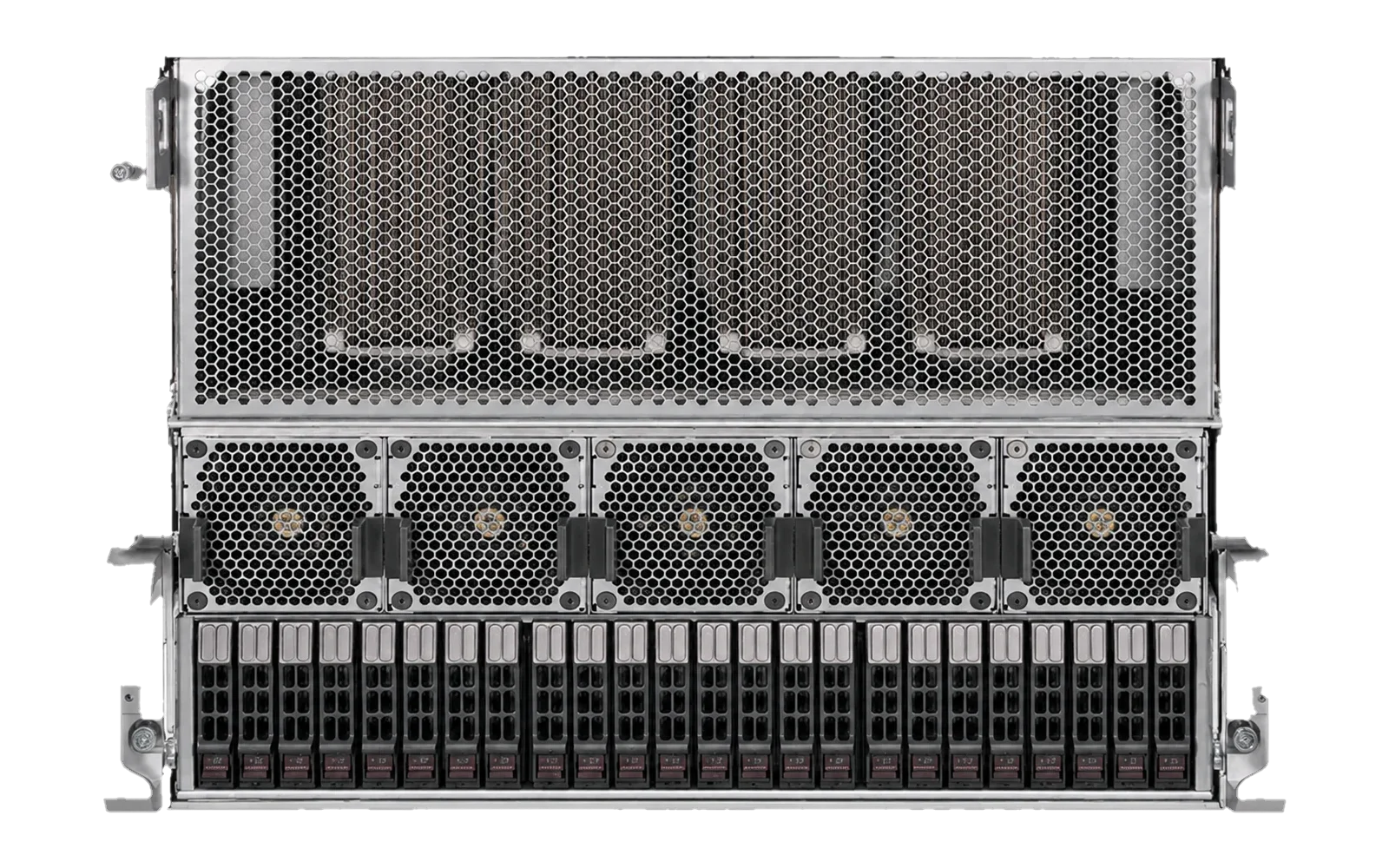 ai infrastructurexSONiC AI Inference ServerPrivate AI inference platform for local LLM, RAG, coding, document intelligence, and multimodal services, with xSONiC deployment support across compute, network, storage, and validation.View product
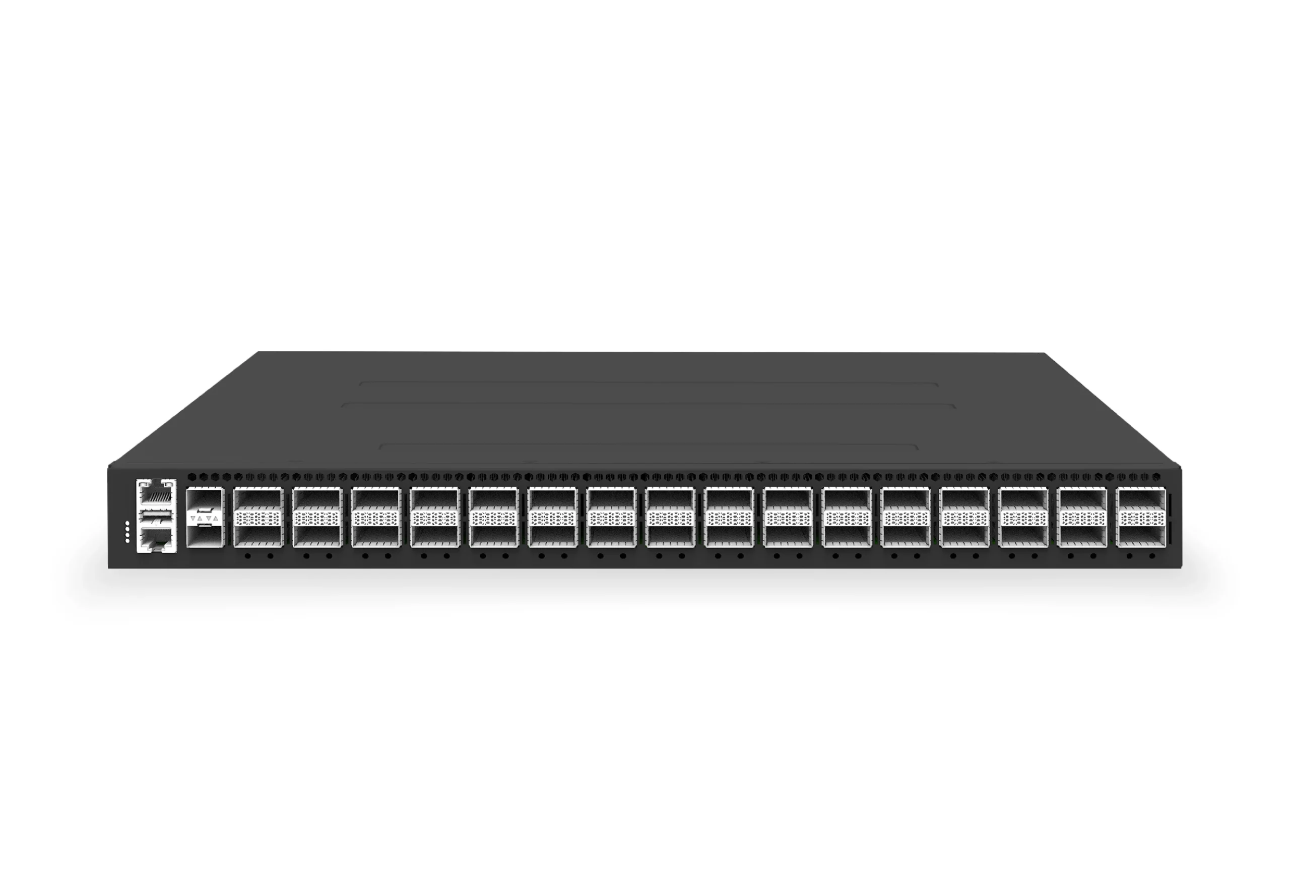 datacenter aiXS-DC-32X400-SP-G232-port 400G spine/core switch for high-capacity data center fabrics and AI-ready backbones.View product
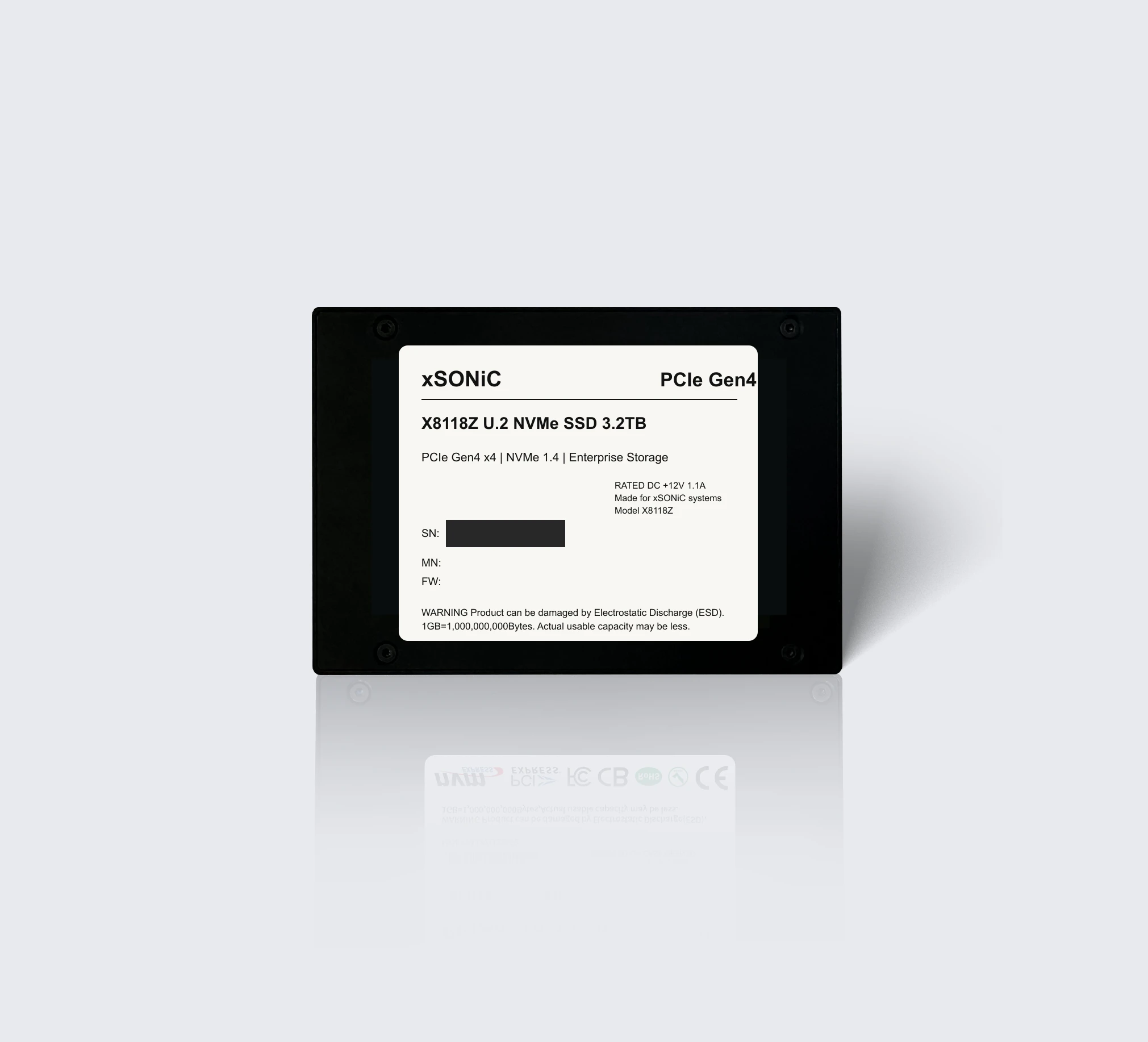 nvme ssdXS-SSD-8118Z-U2Enterprise U.2 NVMe SSD with PCIe Gen4 x4, NVMe 1.4, up to 7.1 GB/s sequential read, and 1,000K IOPS for data center storage workloads.View product
FAQ
Frequently asked questions
How much power does an on-premises LLM server need?
It depends on the complete configured system. Dense eight-GPU platforms can enter the double-digit-kilowatt range, but facilities must use the vendor's configuration-specific maximum input, connector, feed, and redundancy requirements rather than a generic GPU total or article estimate.
Does every inference server require liquid cooling?
No. Cooling requirements vary by accelerator and system configuration. Supported air-cooled systems still require verified airflow and room capacity, while the densest configurations may require a direct-liquid loop and compatible facility heat rejection. Confirm the method before ordering the platform.
Can an LLM server use an existing office network and NAS?
Only after measurement shows that those paths satisfy model-load, RAG, backup, management, and user-ingress requirements. Large sequential model reads and latency-sensitive vector queries behave differently from ordinary office traffic, so assumed link rates and storage labels are not acceptance evidence.
What should LLM deployment acceptance testing include?
Replay a representative request profile on the selected models and precision, record throughput and p50/p95 latency at the required concurrency, test failure and recovery paths, and hand over the dashboards, alerts, configuration record, runbook, and escalation path.
Continue reading
Related articles
 Deployment GuideHow to Run DeepSeek, Qwen, or Llama On-Premises: A Hardware Sizing GuideSize an on-premises open-LLM deployment through five decisions: model variant, precision, GPU memory, serving framework, and measured validation.Read article
 Technical ArticleWhat Is Private AI Infrastructure? A Guide for EnterprisesPrivate AI infrastructure keeps models, prompts, documents, embeddings, and logs inside a controlled environment across compute, network, storage, and operations.Read article
 Technical ArticleWhy Tokens-per-Second Benchmarks Mislead LLM Infrastructure BuyersA token-rate headline changes with model, precision, context, batching, framework, and latency. Learn how to benchmark an inference service honestly.Read article
 Technical ArticleNetwork and Storage Planning for Private AI Inference Servers: A Practical Buyer GuideA practical buyer guide to network and storage planning for private AI inference servers in Australian data centers.Read article
 Technical ArticlePrivate AI Inference GPU Networking Deployment Playbook: Spine-Leaf Fabric Design with SONiCEngineering guidance on Private AI Inference GPU Networking Deployment Playbook for Australian data centre buyers, covering form factor choice, link budgets, cabling.Read article
 Technical ArticleWhy Australian AI Platform Teams Are Rethinking GPU Network Observability for Private InferenceGuide for Australian AI platform teams on GPU network observability, covering telemetry, packet brokers, sovereignty, and inference fabric risk.Read article