In brief
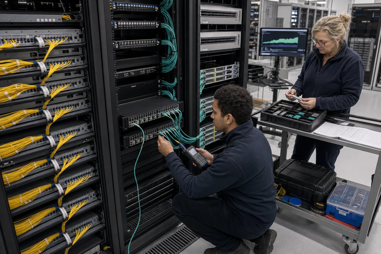
Engineering guidance on Capacity Planning for Network Packet Brokers for Australian network and security teams, covering traffic visibility, capacity modelling, tool.
Key takeaways
- Procurement teams responsible for network visibility infrastructure face a recurring problem: packet broker sizing is often treated as a technical afterthought rather than a structured buying decision.
- In Australian enterprise and data center programs, this challenge is compounded by several market-specific factors.
- This article provides a practical capacity planning model for procurement leads evaluating network packet broker deployments.
Why Procurement Leads Need a Packet Broker Capacity Model
Procurement teams responsible for network visibility infrastructure face a recurring problem: packet broker sizing is often treated as a technical afterthought rather than a structured buying decision. When a security operations center requests full traffic mirroring, or a compliance team demands packet capture for regulatory audits, the result is frequently an undersized or overprovisioned deployment that wastes budget and fails to deliver the visibility the organization actually needs.
In Australian enterprise and data center programs, this challenge is compounded by several market-specific factors. Data sovereignty requirements under the Australian Government’s Hosting Certification Framework mean that traffic visibility infrastructure must be deployed, managed, and audited within Australian borders. Rapid investment in sovereign data center capacity - as highlighted in a 2026 Open Compute Project podcast conversation with David Hirst, CEO of Macquarie Data Centres - is reshaping how Australian organizations think about infrastructure planning, particularly as AI workloads place new demands on network architectures.
This article provides a practical capacity planning model for procurement leads evaluating network packet broker deployments. It covers the core use cases, a sizing framework, and key decision criteria that separate adequate visibility infrastructure from a procurement regret.
The Australian Data Center and Enterprise Visibility Landscape
Australia’s data center market is undergoing significant growth driven by cloud adoption, AI workload migration, and sovereign infrastructure mandates. According to discussion in the OCP community, the Australian market has distinctive characteristics: high compliance expectations, growing demand for liquid cooling and high-density rack designs, and a regulatory environment that favors long-term operators over short-term developers.
For procurement leads, this means packet broker infrastructure must be planned with the same rigor applied to compute and storage capacity. Network visibility is not optional when:
- Security operations centers need full-fidelity traffic for threat detection and forensic analysis.
- Compliance teams require packet capture and retention to meet Australian Privacy Act and industry-specific regulatory obligations.
- AI and machine learning clusters need network telemetry to debug RDMA, RoCE, or congestion issues in GPU backend fabrics.
- Network operations teams rely on traffic flow data for capacity planning and troubleshooting across spine-leaf architectures.
The SONiC (Software for Open Networking in the Cloud) ecosystem, maintained as a Linux Foundation project, provides the open networking foundation that makes disaggregated packet broker architectures viable. SONiC’s containerized, modular design and multi-vendor hardware support give procurement teams an alternative to proprietary, monolithic visibility platforms.
Core Packet Broker Use Cases for Australian Programs
Before sizing a packet broker deployment, procurement leads should map the required use cases. Each use case has different traffic handling characteristics that directly affect capacity requirements.
Traffic Aggregation
Aggregation combines traffic from multiple lower-speed links into fewer higher-speed tool ports. A common pattern in Australian enterprise campuses is aggregating traffic from 10G or 25G access switch uplinks onto 40G or 100G tool interfaces for centralized analysis. This reduces the number of monitoring tool ports required and simplifies cabling.
Procurement consideration: The aggregation ratio determines oversubscription risk. If 8 x 25G links (200 Gbps total) feed into a single 100G tool port, any burst above 100 Gbps will result in packet drops. Your capacity model must account for peak traffic, not average utilization.
Traffic Filtering
Filtering applies rules to pass or drop specific traffic flows before they reach monitoring tools. Use cases include sending only web application traffic to a WAF monitor, forwarding VoIP streams to a call quality analyzer, or excluding bulk storage replication traffic from security tool inputs.
Procurement consideration: Filter rule complexity affects both the number of rules that can be applied and the throughput degradation under load. A packet broker that handles 10,000 filter rules at line rate is a different procurement value than one that degrades significantly beyond 500 rules. Verify filter rule capacity and throughput impact with the vendor before purchase.
Traffic Replication
Replication copies a single traffic stream to multiple monitoring tools simultaneously. A typical data center deployment might replicate a core link’s traffic to a network performance monitor, a security information and event management (SIEM) collector, and a packet capture appliance all at once.
Procurement consideration: Replication multiplies bandwidth. If a 40G link is replicated to four tools, the packet broker must handle 160 Gbps of internal switching. Ensure the backplane capacity of the packet broker supports the total replicated bandwidth across all ports and tools.
Load Balancing
Load balancing distributes traffic across multiple instances of the same monitoring tool to prevent any single tool from being overwhelmed. This is essential for high-throughput environments such as data center interconnects or AI cluster east-west traffic monitoring.
Procurement consideration: Hash-based load balancing can create uneven distribution if traffic patterns are not well-distributed across flow tuples. Understand the load balancing algorithms offered and whether they support L2 through L4 hash fields.
A Capacity Planning Model for Packet Broker Procurement
The following framework helps procurement leads build a defensible sizing model before engaging vendors. It moves beyond port counts to capture the operational variables that determine actual deployment success.
Step 1: Inventory Source Links
Catalog every network link that needs visibility. For each link, record:
- Link speed (1G, 10G, 25G, 40G, 100G, 400G)
- Link type (access uplink, spine-leaf fabric, DCI, WAN, management)
- Average utilization percentage
- Peak utilization percentage (measured, not estimated)
- Whether the link carries symmetric or asymmetric traffic
For Australian data center programs deploying AI workloads, east-west traffic within GPU backend fabrics can exhibit bursty, synchronized patterns that differ substantially from traditional north-south enterprise traffic. This distinction matters for peak utilization estimates.
Step 2: Map Traffic to Use Cases
For each source link, assign one or more use cases (aggregation, filtering, replication, load balancing). Document the expected output:
- How many tool ports will receive traffic from each source?
- What filter rules apply to each use case?
- What is the replication factor (how many copies of each stream)?
Step 3: Calculate Aggregate Bandwidth
Multiply source link bandwidth by the replication factor, then sum across all links. This gives you the total internal switching capacity the packet broker must handle. For example:
- 20 x 25G links replicated 3x = 20 x 25 x 3 = 1,500 Gbps internal bandwidth
- 4 x 100G links replicated 4x = 4 x 100 x 4 = 1,600 Gbps internal bandwidth
- Total: 3,100 Gbps (3.1 Tbps) internal switching requirement
Step 4: Account for Headroom and Growth
Add a growth buffer based on measured peaks, committed projects, and the refresh window. For a defensible procurement model, record the current 95th-percentile traffic level, the measured peak, the replication factor, and the planned 24- to 36-month growth drivers such as 400G adoption, AI fabric expansion, or new compliance capture zones. Avoid treating a fixed percentage as universal; the headroom should be justified by evidence.
Step 5: Evaluate Architecture Fit
With capacity numbers in hand, evaluate whether a chassis-based, fixed-form-factor, or distributed architecture fits the deployment:
- Chassis-based platforms offer modularity and port density but carry higher per-slot costs.
- Fixed-form-factor appliances provide predictable pricing and simpler deployment for mid-sized environments.
- Distributed or clustered architectures suit geographically spread Australian enterprise campuses with regional data centers.
For organizations already running SONiC-based switching fabrics, an open-architecture packet broker that integrates with the same management and telemetry stack can reduce operational complexity. This is where disaggregated, multi-vendor approaches challenge the incumbent proprietary visibility platform model.
Open Networking and the Disaggregated Packet Broker Opportunity
The SONiC ecosystem, supported by the SONiC Foundation under the Linux Foundation, demonstrates that production-grade network functionality can run on multi-vendor hardware with containerized, modular software. The Open Compute Project’s networking initiative extends this principle to switching silicon, ONIE-based provisioning, and SAI (Switch Abstraction Interface) standardization.
For procurement leads evaluating packet broker options, open-architecture approaches offer several advantages:
- Hardware flexibility: Choose from multiple switch vendors rather than being locked to a single platform.
- Software modularity: Deploy traffic processing functions (aggregation, filtering, replication, deduplication, tunnel processing, packet slicing) as independent components.
- Telemetry integration: Align packet broker operations with INT (In-band Network Telemetry) and IPTPath telemetry data already flowing from the switching fabric.
- Cost transparency: Separate hardware cost from software licensing, enabling more granular procurement evaluation.
However, procurement leads should verify that any open-architecture packet broker platform has been validated for the specific use cases and throughput levels their program requires. Open does not mean untested.
Procurement Checklist: 10 Questions Before You Buy
Use this checklist during vendor evaluation:
- What is the maximum sustained throughput at your required filter rule complexity?
- What is the replication factor supported at line rate?
- Does the platform support both aggregation and load balancing on the same ports?
- Can it process tunneled traffic (GRE, VXLAN, ERSPAN) without external decapsulation?
- What deduplication capabilities exist, and at what throughput?
- Does it offer packet slicing for metadata-only delivery to analytics tools?
- What management interfaces are available (CLI, SNMP, REST API, NETCONF/YANG)?
- How does the platform integrate with existing SONiC or open networking fabric management?
- What is the upgrade path for adding capacity without replacing the existing deployment?
- Does the vendor provide Australian-based support and warranty coverage?
Planning for AI Workload Traffic Patterns
Australian data center programs investing in AI infrastructure face a unique visibility challenge. GPU backend fabrics running RoCE v2 or other RDMA protocols generate traffic patterns that are bursty, latency-sensitive, and often synchronized across multiple GPU nodes. Traditional packet broker capacity models based on average utilization can significantly underestimate peak bandwidth requirements.
When planning packet broker capacity for AI fabric monitoring:
- Model peak east-west traffic during training job synchronization phases, not just steady-state inference.
- Account for RoCE v2 congestion notification and priority flow control traffic that may require separate filtering rules.
- Consider whether INT telemetry integration from the switching fabric can supplement or replace full packet capture for certain diagnostic use cases.
This connects directly to the broader AI Fabric and GPU Backend Fabric solution patterns that xSONiC supports across its data center switching portfolio.
Conclusion: Procurement Rigor Prevents Visibility Gaps
A structured capacity planning model gives procurement leads the evidence they need to justify investment, evaluate vendors on comparable terms, and avoid the common trap of sizing packet broker infrastructure for yesterday’s traffic instead of tomorrow’s. In the Australian market, where sovereign data center capacity is expanding rapidly and AI workloads are reshaping network traffic profiles, this planning discipline is more important than ever.
Start with the use case inventory, calculate aggregate bandwidth with replication factored in, add growth headroom, and evaluate architecture fit against your existing network operations stack. The result is a procurement brief that engineering teams, security teams, and finance stakeholders can all align on.
Packet Broker Capacity Acceptance Matrix
| Capacity area | Evidence to capture | Acceptance gate | Rework trigger |
|---|---|---|---|
| Source traffic | Link inventory, 95th percentile, burst peak, packet size mix, tunnel mix, and growth projects | Model includes current 100G/400G links and 12 months planned expansion | Sizing uses average traffic only |
| Replication and filtering | Tool copies, filter count, deduplication, slicing, tunnel handling, and load-balancing rules | 30 minutes replay proves throughput with intended rules enabled | Vendor proof uses clean traffic without production filters |
| Tool capacity | IDS, NDR, forensics, SIEM, storage, and tool-port ingress limits | No sustained drops at broker or tool ingress during peak scenario | Broker is sized but tools are overloaded |
| Resilience | HA pair, bypass behaviour, link failure, tool failure, and config rollback | 3 failure cases captured with packet-loss and recovery evidence | Visibility disappears during the incident window |
| Operations | Change workflow, alerting, evidence bundle, support owner, and audit trail | P1 simulation produces a support-ready packet evidence record within 2 hours | Security and network teams cannot agree which data is authoritative |
Engineering FAQ
What is the first number to calculate when sizing a packet broker? Start with total source bandwidth, then multiply by the replication factor. A 100G source copied to four tools is a 400G internal handling requirement before filtering and load balancing are considered.
Should sizing use average or peak utilisation? Use measured peak and 95th-percentile utilisation, not only averages. Packet visibility designs fail during bursts, and bursts are often when security and operations teams need evidence most.
How much growth headroom is enough? The headroom should be tied to known projects: new 100G/400G links, AI clusters, additional SOC tools, longer retention windows, or more TAP coverage. A generic percentage is weaker than a documented growth model.
What should procurement require from vendors? Ask vendors to prove throughput at the intended filter count, replication factor, tunnel handling mode, deduplication setting, and tool-port mix, not only quote headline switching capacity.
Related xSONiC Resources
Sources Reviewed
- Ethernet Network Adapters - ConnectX NICs | NVIDIA
- NVIDIA BlueField Data Processing Unit
- NVIDIA Spectrum-X Ethernet Platform
- OpenConfig gNMI Specification
- OpenConfig
- RFC 7950 - The YANG 1.1 Data Modeling Language
- RFC 6241 - Network Configuration Protocol (NETCONF)
- ACSC Essential Eight
- OAIC Notifiable Data Breaches
- APRA CPS 234 Information Security
- NETSCOUT Network Packet Definition
- Cloudflare Network Packet Definition
- SONiC Project Documentation
- Broadcom Ethernet Switching
- Marvell Switching
- NVIDIA Ethernet Switching
- Open Compute Networking
- SONiC GitHub
- SONiC Foundation
Product fit
Products referenced for evaluation
These products are referenced for evaluation context in the article. Confirm workload, port, optics, software, interoperability, and support requirements against the exact deployment before procurement.
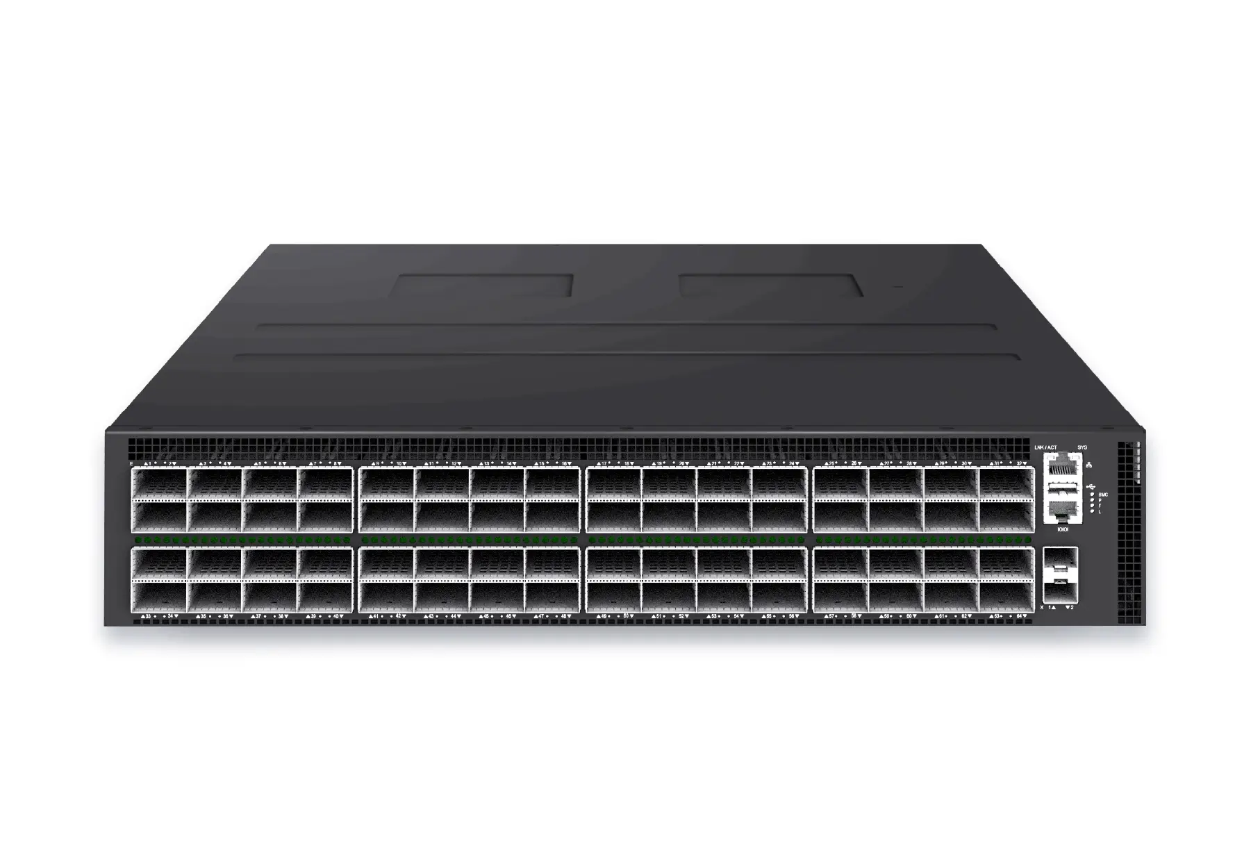 datacenter aiXS-DC-64X800-AI-G164-port 800G AI fabric switch for large-scale GPU clusters, HPC backbones, and ultra-high-throughput data center networks.View product
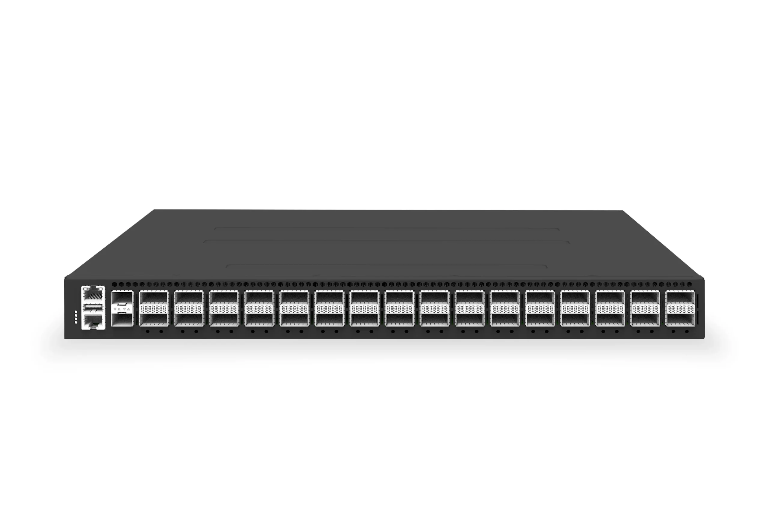 datacenter aiXS-DC-32X400-SP-G232-port 400G spine/core switch for high-capacity data center fabrics and AI-ready backbones.View product
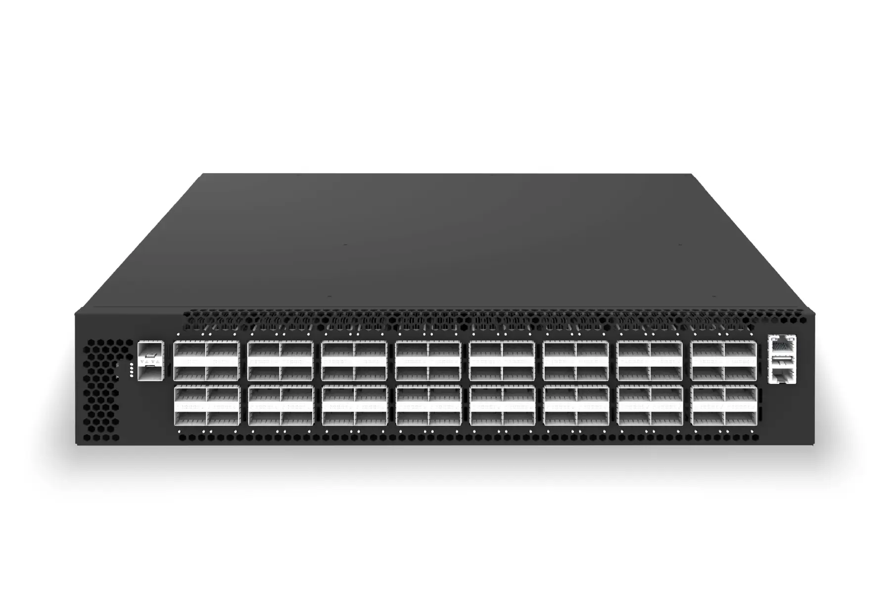 datacenter aiXS-DC-64X200-LS-G164-port 200G leaf/spine switch for high-bandwidth storage, compute, and scale-out data center fabrics.View product
Continue reading
Related articles
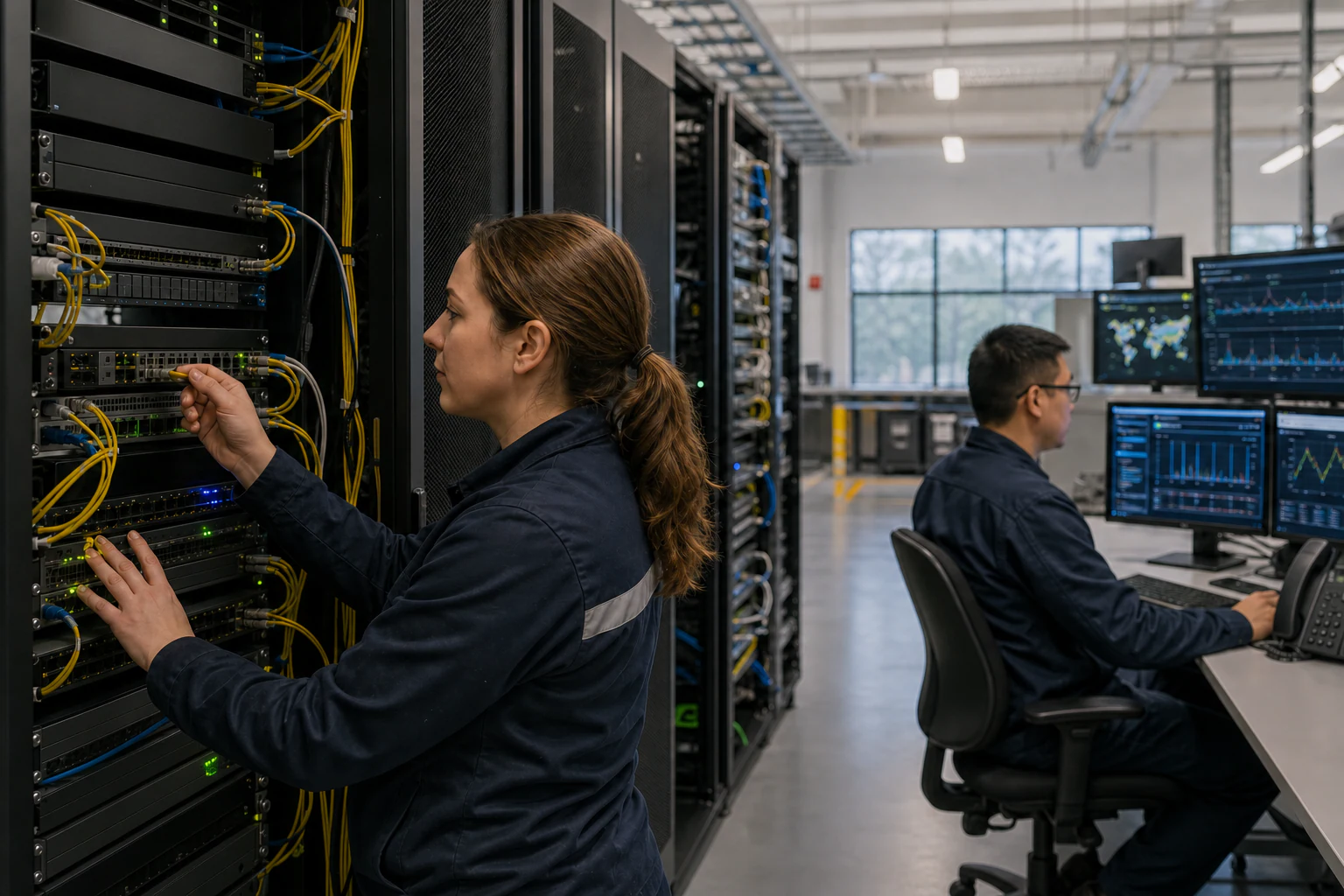 Technical ArticleHow Packet Brokers Filter, Replicate and Load-Balance TrafficEngineering guide for packet broker and visibility planning covering traffic capacity, filtering, tool delivery, resilience, and audit evidence.Read article
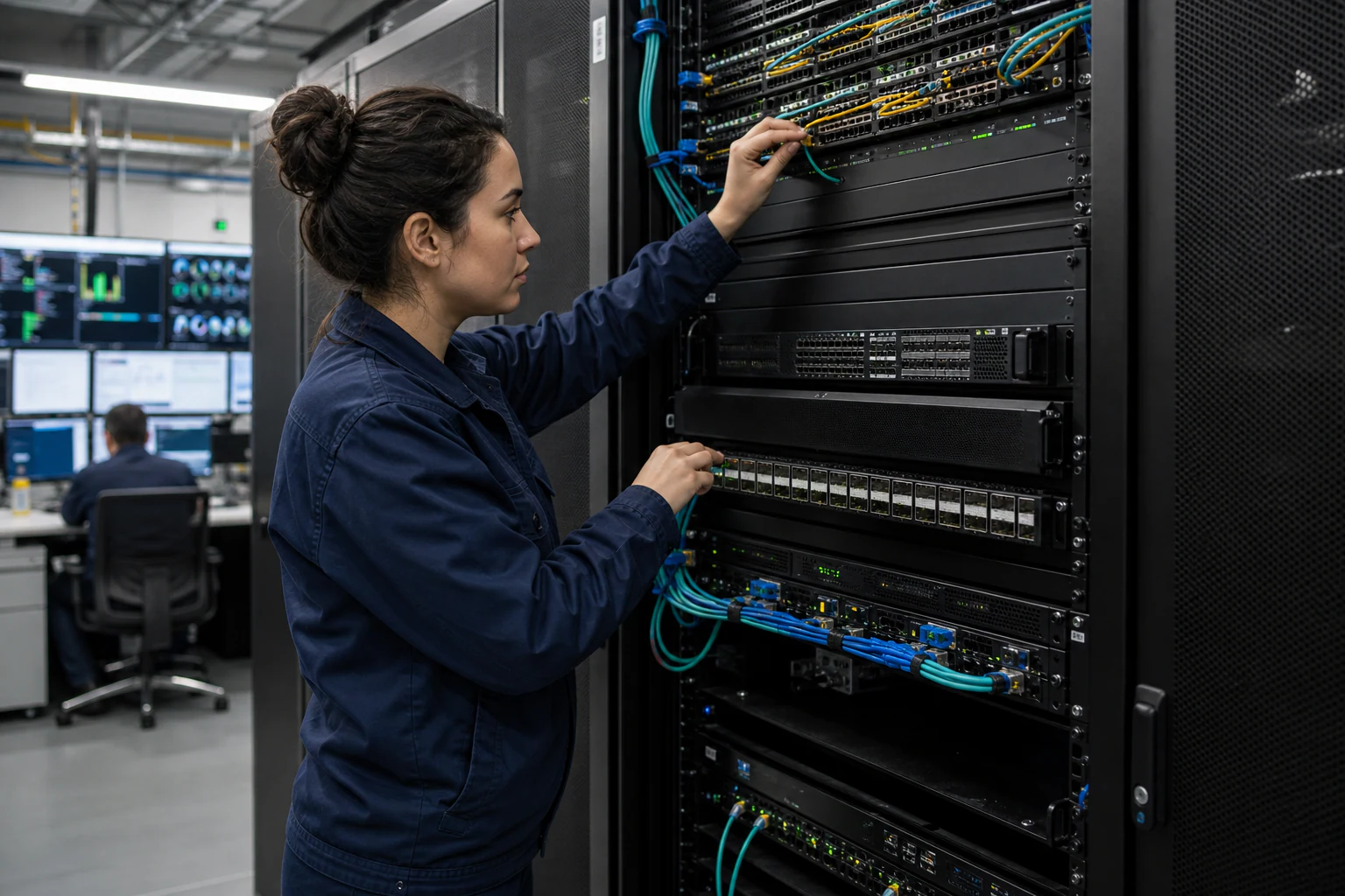 Technical ArticlePacket Broker Use Cases for Network Visibility and Observability: A Practical Guide for Australian EnterprisesEngineering use cases for packet brokers in observability, performance troubleshooting, AI fabrics, compliance capture, and multi-tool delivery.Read article
 Technical ArticleWhy AI Data Centers Need In-Band Network Telemetry -- And Where Open SONiC FitsINT and path telemetry guide for AI fabric observability, covering SONiC support, RoCE congestion, telemetry pipelines, and buyer risk.Read article