In brief
Engineering guidance on Virtual Chassis and Cluster Failure-Mode Review for Australian campus teams, covering PoE budgets, access-layer resilience, migration risk.
Key takeaways
- Virtual chassis and switch cluster designs are the backbone of most Australian enterprise campus networks.
- Unlike a standalone switch failure that affects one floor or one building, a virtual chassis control-plane failure can take down the entire logical switch stack simultaneously.
- Australian enterprises face an additional consideration: data sovereignty and compliance obligations under frameworks such as the Australian Government Information Security Manual (ISM), the Critical Infrastructure Act 2018 (as amended), and APRA CPS 234 for financial services.
Why Failure-Mode Review Matters for Virtual Chassis and Cluster Topologies
Virtual chassis and switch cluster designs are the backbone of most Australian enterprise campus networks. They promise a single management plane, simplified configuration, and fast failover. However, when they fail, the blast radius is campus-wide.
Unlike a standalone switch failure that affects one floor or one building, a virtual chassis control-plane failure can take down the entire logical switch stack simultaneously. In a five-member virtual chassis, a firmware bug in the control plane or a split-brain condition between dual management modules can cascade into a complete campus outage.
Australian enterprises face an additional consideration: data sovereignty and compliance obligations under frameworks such as the Australian Government Information Security Manual (ISM), the Critical Infrastructure Act 2018 (as amended), and APRA CPS 234 for financial services. A campus-wide switching outage that disrupts connectivity to cloud-hosted sovereign workloads or triggers a security control bypass is not just an operational inconvenience; it is a compliance event.
This guide gives network architects a structured way to identify, categorize, and remediate failure modes before they reach production. It applies to both traditional closed-vendor virtual chassis stacks and open networking architectures running Enterprise SONiC on disaggregated hardware.
The SONiC Foundation describes SONiC as an open source network operating system that runs on switches from multiple vendors and ASICs, offering container-based architecture with better fault isolation compared to monolithic switch software (sonicfoundation.dev). This architectural difference matters for failure-mode analysis because a containerized NOS limits the blast radius of individual component failures. For Australian campus programs evaluating open networking as part of a campus refresh, understanding these failure-mode differences is a critical planning step.
Virtual Chassis vs. MC-LAG vs. STP Clustering: Decision Criteria Matrix
Before conducting a failure-mode review, the network architect must confirm the correct redundancy topology for the campus deployment. The three dominant approaches each carry distinct risk profiles.
Decision Criteria Comparison Table:
| Criterion | Virtual Chassis | MC-LAG (Active-Active) | STP-Based Clustering (Traditional Stack) |
|---|---|---|---|
| Management plane | Single (shared control plane) | Dual (independent per peer) | Single (master/backup election) |
| Single point of failure | Control plane module, backplane fabric | Peer-link or keepalive path | Master switch or stack ring |
| Firmware upgrade impact | Full chassis reload required in most implementations | Rolling upgrade possible per peer | Full stack reload in most implementations |
| Split-brain risk | Moderate (dual RE designs reduce this) | High if keepalive path fails | Moderate to high depending on election protocol |
| ASIC diversity | Typically single vendor, single ASIC | Can span different ASIC generations | Typically single vendor |
| Open networking compatibility | Limited in legacy stacks; available in Enterprise SONiC virtual chassis implementations | Well supported in SONiC with dual-homing via MLAG | STP features available in SONiC; stacked designs vendor-dependent |
| Campus scale sweet spot | 200 to 2000 ports per logical switch | 2 to 4 switch pairs at aggregation/core | Small to medium campus (up to 400 ports) |
| Australian compliance advantage | Simpler audit surface (one logical device) | No single control-plane dependency for critical links | Familiar model for incumbent operations teams |
When to choose virtual chassis: You need a single management domain for a medium-to-large campus floor or building, your operations team can manage firmware lifecycle as a single coordinated event, and your change window tolerance is at least a full maintenance cycle.
When to choose MC-LAG: You need active-active uplinks from access switches, your critical aggregation or core layer cannot tolerate a control-plane single point of failure, or you are running a disaggregated campus fabric with SONiC on multiple hardware platforms.
When to choose STP clustering: Your campus is small (under 400 switch ports), your team is experienced with spanning-tree troubleshooting, and your budget or timeline does not allow for MC-LAG complexity.
For Australian enterprises evaluating open networking, xSONiC access and aggregation switches running Enterprise SONiC support MLAG and STP configurations that allow the network architect to choose the redundancy model that fits the risk profile, rather than being locked into a single vendor’s virtual chassis implementation. See the xSONiC Virtual Chassis guide and the MC-LAG/STP guide for architecture-level reference designs.
Failure Mode Category 1: Control Plane and Management Plane Risks
The control plane is the highest-risk layer in any virtual chassis or cluster design. A failure here does not just affect management access; it can disrupt routing adjacencies, break DHCP relay, and collapse the entire logical switch.
Failure modes to review:
-
Control-plane CPU saturation. A broadcast storm, ARP flood, or routing protocol flap can overwhelm the shared control-plane CPU in a virtual chassis. In a stack of five switches, all five share one logical control plane. Verify that storm control thresholds, ARP rate limiting, and control-plane policing (CoPP) are configured on every member.
-
Split-brain between dual routing engines. Many enterprise virtual chassis platforms support dual RE (routing engine) designs. If the inter-RE heartbeat path (typically a dedicated backplane link) fails, both REs may believe they are master. This causes duplicate IP addresses, conflicting routing decisions, and traffic blackholing. Review the split-brain detection mechanism: does it use a dedicated out-of-band keepalive, an in-band L2 probe, or a third-party watchdog?
-
Management plane lockout. If the virtual chassis management interface is on a VLAN that traverses the chassis backplane, a backplane failure can lock out all remote management. Always verify that at least one out-of-band management path (console server, dedicated management Ethernet port, or serial console) exists for every member switch.
-
Firmware image corruption. A failed firmware upgrade on one member switch in a virtual chassis can leave the chassis in an inconsistent state where some members run different firmware versions. This can cause protocol mismatches, feature incompatibilities, and unpredictable forwarding behavior. Verify that the platform supports atomic firmware upgrade with rollback.
-
Container service failure (SONiC-specific). SONiC uses a containerized architecture where each network function runs in its own Docker container (sonicfoundation.dev, github.com/sonic-net/SONiC). A container crash (for example, the BGP container or the DHCP relay container) does not necessarily crash the entire switch, but it can disrupt the specific service. Verify that container health monitoring and automatic restart policies are configured, and that critical services (routing, DHCP relay, SNMP) have watchdog mechanisms.
Review blocker: If the campus deployment relies on a single virtual chassis with no out-of-band management path and no dual-RE split-brain detection, this must be flagged as a high-severity review blocker before deployment approval.
Failure Mode Category 2: Data Plane and Forwarding Risks
Data plane failures in a virtual chassis or cluster can be harder to detect than control-plane failures because the management plane may remain accessible while traffic is silently dropped or misforwarded.
Failure modes to review:
-
Backplane fabric link failure. In a virtual chassis, member switches connect through dedicated backplane links (often 10G, 40G, or 100G interconnects). If one or more fabric links fail, the chassis may lose bandwidth capacity or, in some designs, lose reachability to downstream ports on the affected member. Verify that the platform supports fabric link redundancy (N+1 fabric links) and that the chassis degrades gracefully rather than failing hard.
-
Hash polarization. When multiple links in a virtual chassis fabric use the same hashing algorithm, traffic can polarize onto a single link, causing congestion and packet drops while other links remain idle. This is especially dangerous for campus networks carrying a mix of large file transfers and real-time voice/video traffic. Review the ECMP and LAG hash configuration across all fabric links.
-
Black-hole after member failure. When a member switch in a virtual chassis fails, the control plane must withdraw all routes and MAC addresses associated with that member’s ports. If the withdrawal is slow or incomplete, traffic may continue to be forwarded toward the failed member, causing a silent black-hole. Verify the convergence time for member failure detection and route withdrawal.
-
MTU mismatch across virtual chassis members. In mixed-generation virtual chassis stacks, different member switches may have different maximum MTU capabilities. If jumbo frames are enabled on some members but not all, large packets will be silently dropped at the boundary. This is a common cause of intermittent application failures that are difficult to diagnose.
-
ASIC forwarding table exhaustion. Campus aggregation switches in a virtual chassis may run out of MAC address table entries, ARP entries, or route entries as the campus grows. A table overflow condition can cause flooding, black-holing, or even a control-plane crash. Review the platform’s forwarding table capacity against the expected campus scale (number of VLANs, MAC addresses, and routes).
The OCP Networking project notes that its scope includes fully disaggregated and open networking hardware and software, with the goal of giving end users the ability to use fully open network technology stacks rather than traditional closed and proprietary switches (opencompute.org/projects/networking). For Australian enterprises considering disaggregated campus switching, verifying ASIC table capacities and data-plane failure behavior against the specific open hardware platform is a critical pre-deployment step.
Review blocker: If the campus design has more than 4000 MAC addresses and the target virtual chassis platform has not been validated for that scale, this is a review blocker. If fabric link redundancy is N+0 (no redundancy), this is a review blocker.
Failure Mode Category 3: Split-Brain and Network Partition Risks
Split-brain is the most feared failure mode in virtual chassis and cluster designs because it creates two independent control planes that believe they are both authoritative. The consequences range from duplicate IP addresses to routing loops to complete campus meltdown.
Failure modes to review:
-
Virtual chassis split-brain. In a dual-RE virtual chassis, a split-brain occurs when the heartbeat between the two routing engines fails but both remain operational. Each RE may continue to program the forwarding plane independently, causing conflicting forwarding decisions. Verify the split-brain resolution mechanism: does the platform use a deterministic tie-breaker (for example, lowest RE slot ID wins), or does it require manual intervention?
-
MC-LAG peer-link failure without keepalive. In an MC-LAG design, if the peer-link fails and the keepalive path also fails, both peers will believe the other is dead and attempt to take over all active-forwarding roles. This can cause duplicate MAC addresses on the network and traffic loops. Verify that the keepalive path is physically diverse from the peer-link (for example, keepalive via a management network or a dedicated out-of-band link).
-
STP bridge assurance failure. In STP-based campus clusters, bridge assurance is a mechanism that detects unidirectional link failures. If bridge assurance is not enabled, a unidirectional link failure can cause one switch to believe a port is blocked while the other believes it is forwarding, creating a loop. Verify that bridge assurance is enabled on all inter-switch links.
-
VRRP/VRRP-like master conflict. In virtual chassis designs that use VRRP or a similar first-hop redundancy protocol for gateway redundancy, a split-brain condition can cause two VRRP masters. Both will respond to ARP requests, causing clients to receive inconsistent gateway MAC addresses. Verify VRRP preemption, priority, and advertisement interval settings.
-
Asymmetric routing after partition heal. When a network partition heals (for example, a failed virtual chassis member rejoins), the convergence process can create a window where routing is asymmetric. Traffic may take a suboptimal path while routing protocols reconverge. Verify that the design includes dampening or graceful restart mechanisms to prevent route flapping during partition healing.
Review blocker: If the virtual chassis or MC-LAG design has no split-brain detection mechanism or relies solely on in-band keepalive without an out-of-band path, this is a high-severity review blocker.
Engineering FAQ
What should be tested before moving campus switching to SONiC or open networking? Test PoE behaviour, NAC integration, VLAN and policy design, STP or MC-LAG interaction, multicast, monitoring, upgrade rollback, and help-desk workflows. Campus readiness is an operations test, not only a forwarding test.
Where do campus refresh projects usually carry hidden risk? The risk often sits in closets: power budget, old cabling, undocumented uplinks, mixed endpoint types, voice devices, cameras, badge systems, and change windows. Those details should be inventoried before selecting switch models.
How should Australian campus teams structure a pilot? Choose one representative site or building, document endpoint classes, run PoE and failover tests, verify monitoring, train operations staff, and define rollback steps before expanding to the broader estate.
Related xSONiC Resources
Sources Reviewed
- IEEE 802.1Q Bridges and Bridged Networks
- IEEE 802.1AX Link Aggregation
- Ethernet Network Adapters - ConnectX NICs | NVIDIA
- NVIDIA BlueField Data Processing Unit
- NVIDIA Spectrum-X Ethernet Platform
- ACSC Essential Eight
- OAIC Notifiable Data Breaches
- APRA CPS 234 Information Security
- NETSCOUT Network Packet Definition
- Cloudflare Network Packet Definition
- SONiC Project Documentation
- Broadcom Ethernet Switching
- Marvell Switching
- NVIDIA Ethernet Switching
- Open Compute Networking
- SONiC GitHub
- SONiC Foundation
Product fit
Products referenced for evaluation
These products are referenced for evaluation context in the article. Confirm workload, port, optics, software, interoperability, and support requirements against the exact deployment before procurement.
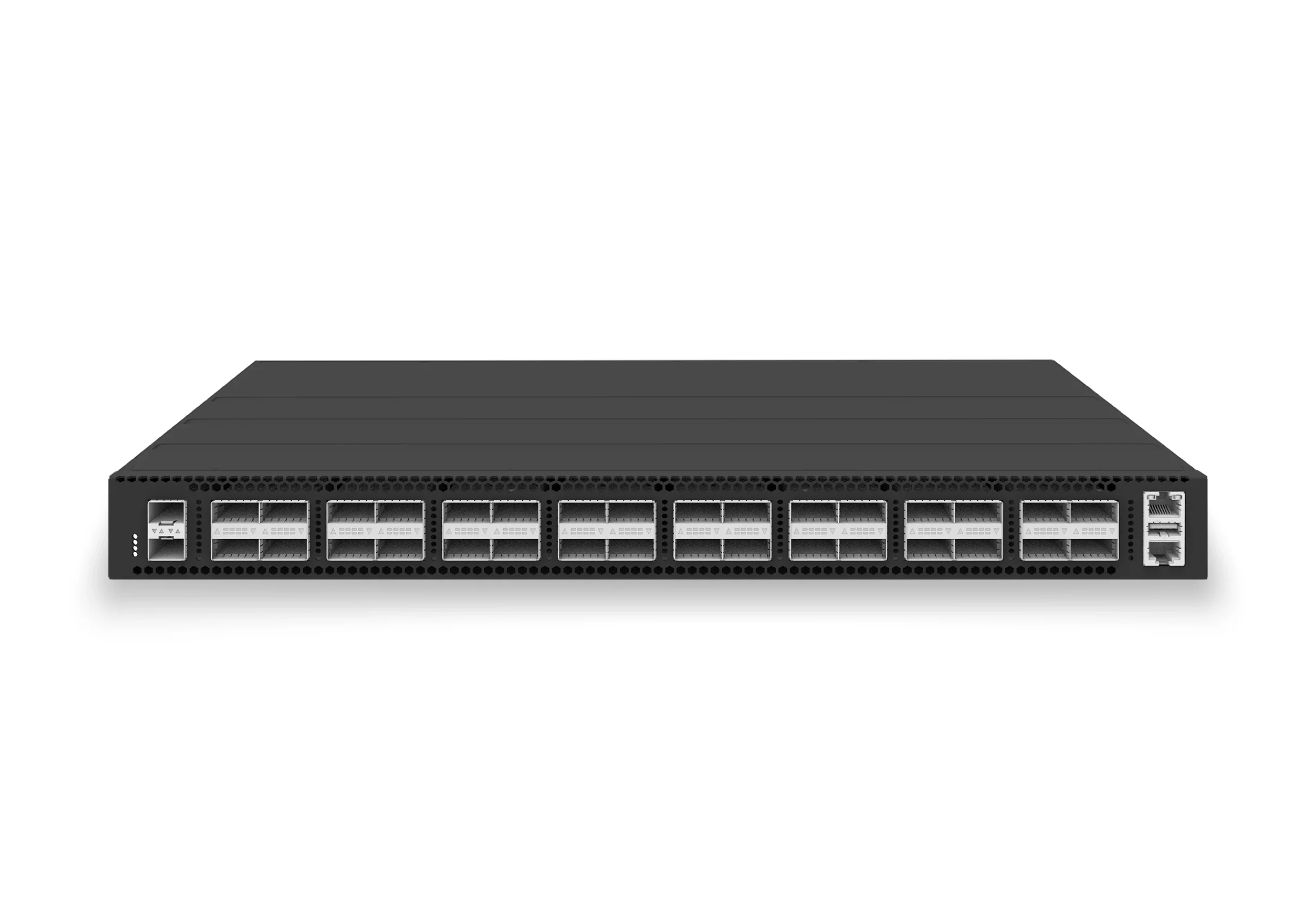 datacenter aiXS-DC-32X100-LS-G232-port 100G leaf/spine switch for VXLAN fabrics, RoCE-ready workloads, and tenant-scale routing.View product
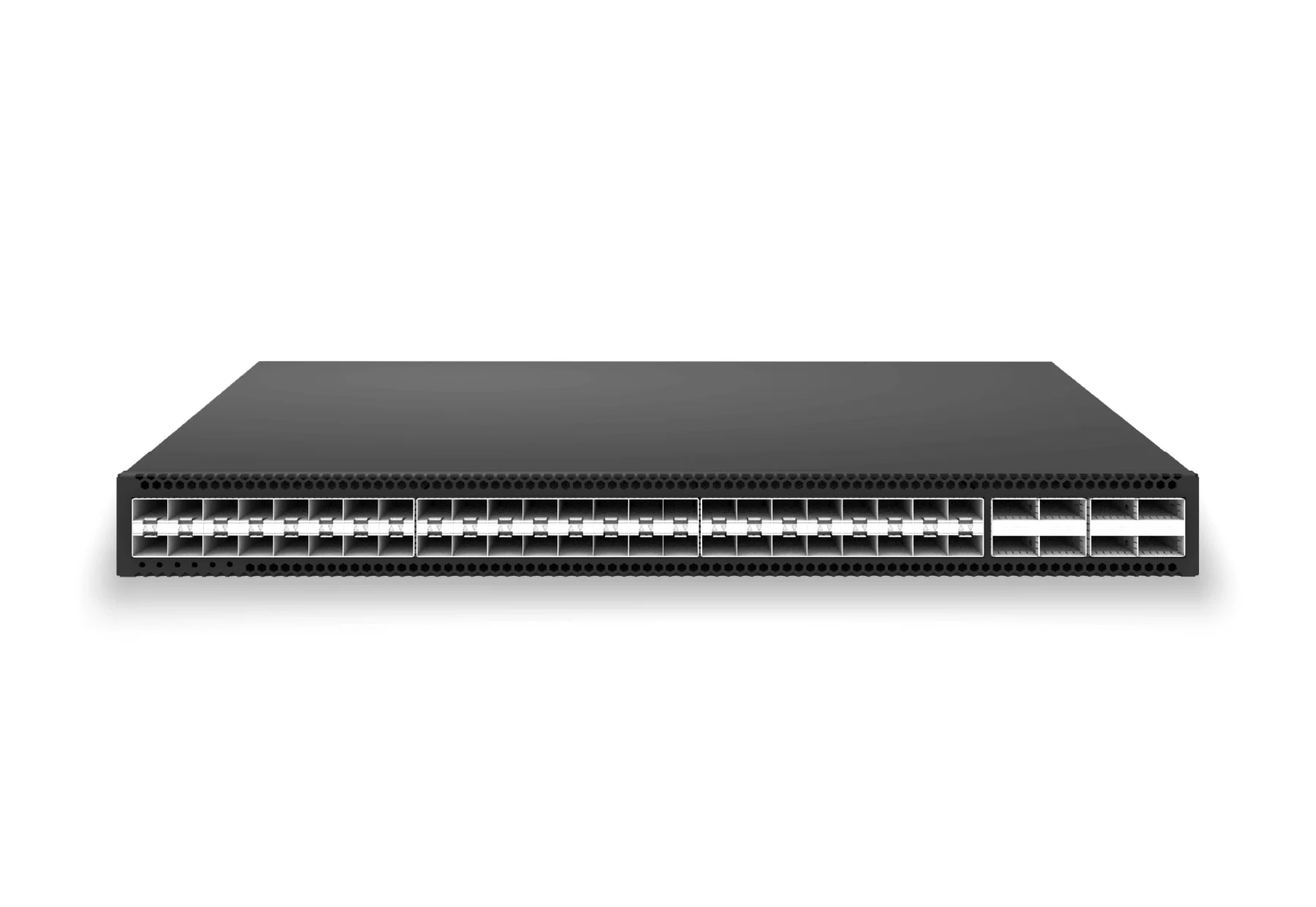 access aggregateXS-AA-48X25-8X100-AGG48x 25G SFP28 aggregation/core switch with 8x 100G QSFP28 for enterprise access and aggregation networks.View product
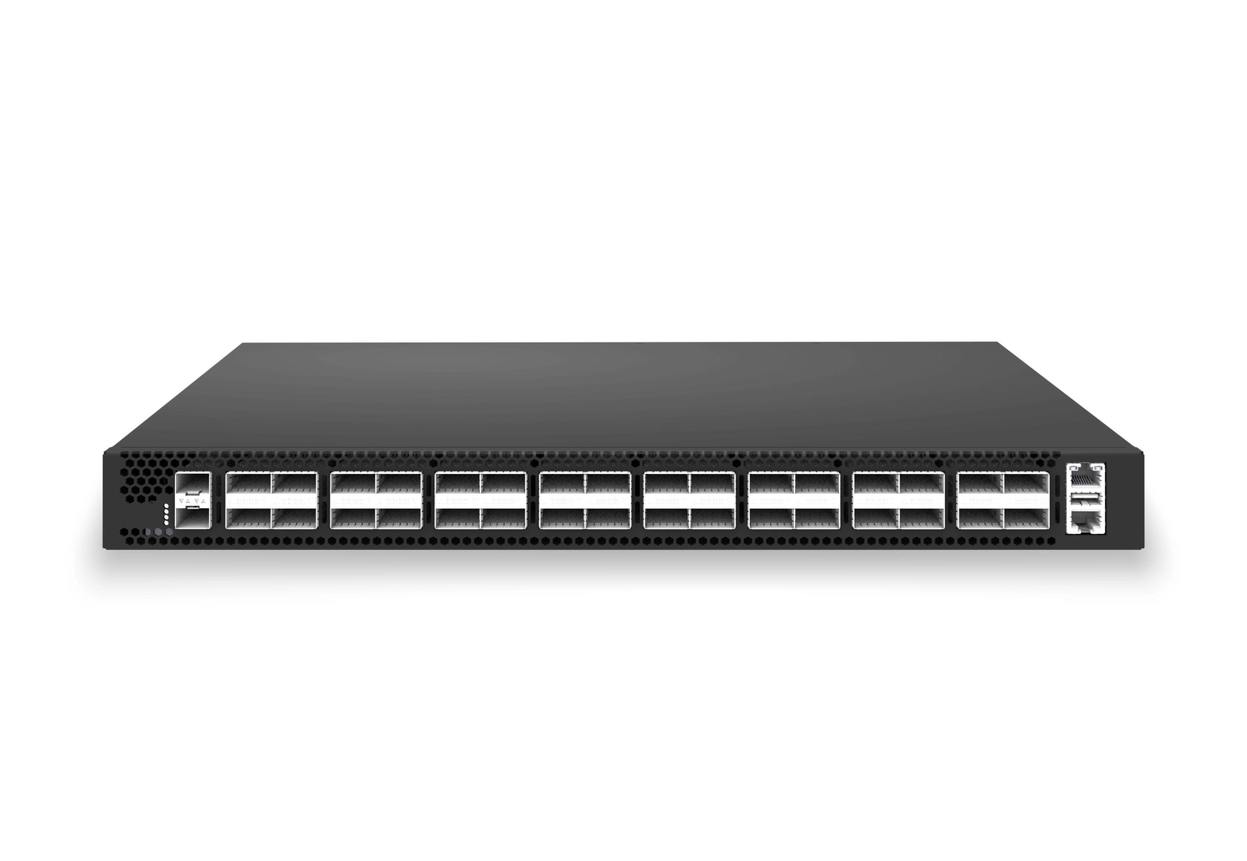 access aggregateXS-AA-32X100-CORE32x 100G QSFP28 aggregation/core switch with 2x 10G SFP+ auxiliary for enterprise access and aggregation networks.View product
Continue reading
Related articles
 Technical ArticleWi-Fi 6E/7 Access Point Planning for Australian Enterprise CampusesA practical Wi-Fi 6E and Wi-Fi 7 access point planning guide for Australian campuses covering 6 GHz spectrum, PoE++, backhaul, client readiness, and pilot validation.Read article
 Technical ArticlePoE Campus Planning Checklist for Enterprise SONiC Access SwitchesEngineering guidance on PoE Campus Planning Checklist for Enterprise SONiC Access Switches for Australian campus networks, covering RF planning, security controls.Read article
 Technical ArticleEnterprise Campus PoE Refresh with SONiC Open NetworkingEngineering guide for campus switching teams covering PoE, access design, MC-LAG/STP risk, telemetry, support, and pilot validation.Read article